
Software phase-locked loop applicable to nonideality power grid condition

A software phase-locked loop, non-ideal technology, applied in electrical components, circuit devices, AC network circuits, etc., can solve problems such as loss of power signal control capability, protection system tripping, and large harmonic content

Inactive Publication Date: 2016-02-24
ANHUI UNIV OF SCI & TECH
View PDF2 Cites 0 Cited by
  • Summary
  • Abstract
  • Description
  • Claims
  • Application Information

AI Technical Summary

Problems solved by technology

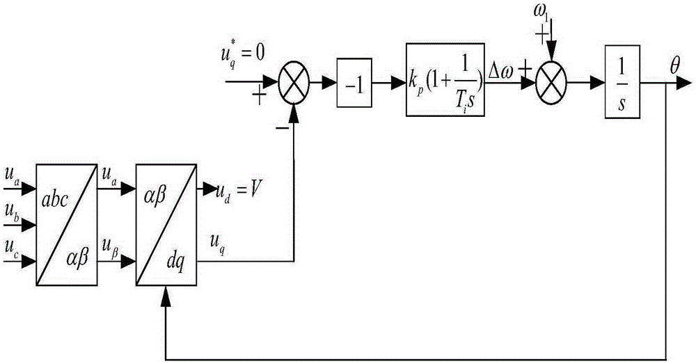
[0003] In the case of a non-ideal grid (three-phase grid voltage imbalance or large harmonic content), the traditional PLL method based on the dq synchronous rotating coordinate system will produce a large deviation when tracking the angle, which will cause the converter control system to lose alignment. The control capability of the power signal will cause the protection system to trip, or even damage the grid-connected converter

Method used


Image

  • Software phase-locked loop applicable to nonideality power grid condition
  • Software phase-locked loop applicable to nonideality power grid condition
  • Software phase-locked loop applicable to nonideality power grid condition

Examples


Embodiment 1

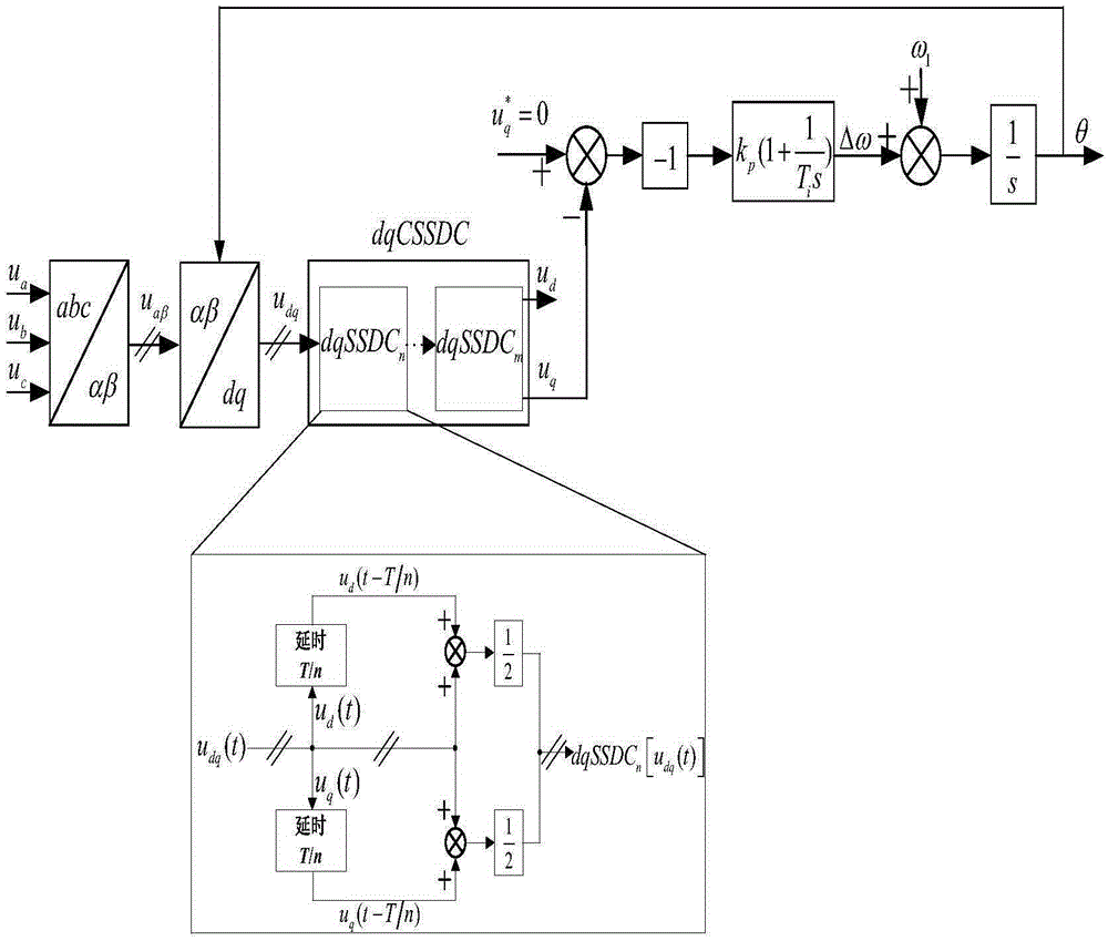
[0102] Such as figure 2 As shown, under the dq coordinates, the control strategy for eliminating harmonics is as follows:

[0103] (a) The three-phase grid voltage is transformed by 3 / 2 rotation to obtain the orthogonal voltage value μ in the stationary coordinate system α , μ β ;

[0104] (b) According to the estimated grid angle to μ α , μ β Do a synchronous rotation transformation to get μ d , μ q ;

[0105] (c) Define the SSDC operator under dq coordinates as dqSSDC n [ v ( t ) ] = 1 2 [ v ( t ) + v ( t - T n ] ;

[0106] (d) μ obtained by synchronous rotation transformation d , μ q Transform the SSDC operator in the dq coordinates...

Embodiment 2

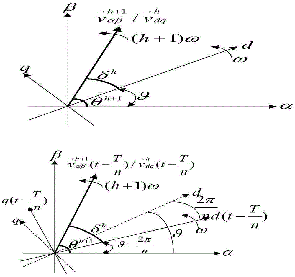
[0109] Such as image 3 , Figure 4 As shown, under the αβ coordinates, the control strategy for eliminating harmonics is as follows:

[0110] (a) Transform the dqSSDC operator to the αβ coordinate system by coordinate transformation, and the harmonic space vector in the dq coordinate system The corresponding quantity in the αβ coordinate system is The transformed angle is The corresponding quantity in the αβ coordinate system is The transformed angle is

[0111] (b) The three-phase grid voltage is transformed by 3 / 2 rotation to obtain the orthogonal voltage value μ in the stationary coordinate system α , μ β ;

[0112] (c) Define the SSDC operator in the αβ coordinates as

[0113] αβSSDC n [ v → α β h ( t ) ] = 1 2 ...


PUM


Abstract

The invention discloses an enhancement type software phase-locked loop which is applicable to a nonideality power grid condition and is based on the cascade sine signal delay cancellation (CSSDC), and the invention is also called CSSDC-PLL for short. The CSSDC-PLL consists of a CSSDC operator and a PLL. The invention relates to the technology fields like the power grid voltage signal detection, the distributed power supply grid connected, etc. For the nonideality power grid condition, the traditional PLL method which is based on the dq synchronization rotating coordinate system generates a relatively big deviation when tracking the angle, which causes the converter control system to lose the control capability over the power signal, causes the protection system to trip and even damages the grid connected converter. The CSSDC-PLL method performs improvement on the traditional PLL method; the CSSDC operator performs processing on the input signal and eliminates the harmonic wave component in the input signal; and the residual pure signals are inputted into PLL. As a result, the PLL bandwidth is set to be very high, which obtains the good system dynamic performances and eliminates the stable state error of the harmonic wave component. The software phase-locked loop applicable to nonideality power grid condition is excellent in harmonic wave elimination capability, transient response speed, etc.

Description

technical field [0001] The invention relates to an enhanced software phase-locked loop CSSDC-PLL based on a cascaded sinusoidal signal delay cancellation (CascadeSineSignalDelayCancellation, CSSDC) method suitable for a non-ideal power grid. It includes CSSDC operator structure design and basic PLL structure design, and belongs to the technical fields of power grid voltage signal detection, distributed power grid connection technology, etc. Background technique [0002] PLL (Phase-Locked Loop, phase-locked loop) is an effective method to obtain the angle of the grid voltage synthesis vector, and is widely used in the technology of connecting distributed power sources with grid-connected converters to the grid. In the case of an ideal power grid, it can quickly and accurately track the angle of the grid voltage synthesis vector. [0003] In the case of a non-ideal grid (three-phase grid voltage imbalance or large harmonic content), the traditional PLL method based on the dq ...

Claims


Application Information

Patent Timeline
IPC IPC(8): H02J3/01H02J3/38H03L7/08
CPCH02J3/01H02J3/381H03L7/08Y02E40/40
Inventor 周小杰陈华森陈静蒋正凯
Owner ANHUI UNIV OF SCI & TECH
Learn More