
A safety valve aging detection method and detection tool for lead-acid batteries

A lead-acid battery and testing tooling technology, applied in the field of testing, can solve the problems of sticking between the valve body and the valve seat, reducing the battery cycle life, and failing to open the opening pressure of the safety valve, so as to achieve high reliability, avoid premature termination, and prevent The effect of qualified safety valve

Active Publication Date: 2017-12-26
FENGFAN
View PDF3 Cites 0 Cited by
  • Summary
  • Abstract
  • Description
  • Claims
  • Application Information

AI Technical Summary

Problems solved by technology

The problems of this traditional detection method are: 1. The safety valve is buckled upside down on the valve seat when it is used, and it will be subjected to mechanical stress for a long time, which will accelerate its aging process, and the acid dipping detection method cannot reflect the above process; 2. The battery When in use, the interior of the battery cell is in a negative pressure state most of the time, and the safety valve is tightly attached to the valve seat. The adhesion between the valve body and the valve seat may occur due to long-term negative pressure, so that the safety valve cannot be opened or the opening pressure is too large. , and the negative pressure state cannot be simulated by the pickling detection method
Based on the above factors, the traditional safety valve aging detection method cannot truly reflect the aging state of the safety valve, so that some unqualified products can pass the aging detection and be used on the battery. As a result, the cycle life of the battery is greatly reduced, and even the battery is bulging. Vicious accidents such as explosions

Method used


Image

  • A safety valve aging detection method and detection tool for lead-acid batteries
  • A safety valve aging detection method and detection tool for lead-acid batteries
  • A safety valve aging detection method and detection tool for lead-acid batteries

Examples


Embodiment Construction

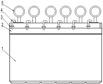
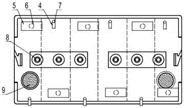
[0024] The safety valve is a rubber product, and its structure is as follows: image 3 shown. The installation method of the safety valve is to buckle it on the valve seat by means of interference fit, weld the cover piece on the air passage, keep a distance of about 0.5mm between the top of the safety valve and the upper cover piece, when the internal pressure of the pole group is too large, the safety The valve slides up to the position of the cover piece, the lower part of the safety valve is opened to release air, and when the air pressure drops to a certain level, the safety valve closes. During the aging process of the safety valve, the performance gradually declines and the use value gradually loses. On the one hand, the safety valve is subjected to mechanical stress for a long time, which accelerates the aging of the rubber; on the other hand, during the use of the battery, most of the time inside the cell is in a negative pressure state, and the safety valve is close...


PUM

PropertyMeasurementUnit
densityaaaaaaaaaa

Abstract

The invention relates to a safety valve ageing detection method and a detection tool used for a lead acid storage battery. The detection method comprises the following steps: randomly extracting six safety valves from a same batch of the safety valves as detection samples; arranging all the detection samples on the valve seats of the detection tool, and measuring and recording the valve opening pressures and the valve closing pressures of the detection samples before ageing one by one; taking the detection samples from the valve seats, smearing the inner walls of all the detection samples with a sulfuric acid solution, and re-arranging the detection samples on the valve seats; carrying out vacuum pumping on all unit cells of the detection tools to -15kPa; disposing the detection tool at 60DEG C for 5d, and cooling to room temperature; measuring and recording the first valve opening valves and the valve closing pressures of all the detection samples one by one after ageing; and determining according to the detection result. The method allows the ageing performances of the safety valves to be objectively, really and accurately reflected, maximally avoids use of unqualified safety valves in the storage battery, and avoids early termination of the cycle life of the battery due to too early failure of the safety valves.

Description

technical field [0001] The invention relates to a detection method, in particular to a safety valve aging detection method and detection tooling for lead-acid storage batteries, and to the technical field of storage batteries. Background technique [0002] The safety valve is one of the key components of the lead-acid battery. It is installed on the top of the lead-acid battery. Its main functions are: 1. Sealing function. When the internal pressure of the battery is lower than the closing pressure of the safety valve, the safety valve is closed to prevent air from entering the electrode group to oxidize. The negative plate causes the battery capacity to drop, and also prevents the internal gas acid mist from leaking out. 2. Safety function. When the gas pressure generated inside the battery reaches the pressure of the safety valve during the use of the battery, the safety valve opens to release the pressure to prevent battery deformation and rupture. 3. Ensure the normal i...

Claims


Application Information

Patent Timeline
Patent Type & Authority Patents(China)
IPC IPC(8): H01M10/48
CPCH01M10/482Y02E60/10
Inventor 王丽斋张玉孙晓飞张利芳韩二莎
Owner FENGFAN
Learn More