
Double-light-beam synthesis sensor by utilizing single detector to perform optical pupil and optical axis regional imaging

A technology for synthesizing sensors and detectors, which is applied in the field of optical engineering, can solve problems such as reducing the use of detectors, achieve the effects of improving measurement consistency and stability, reducing system or equipment costs, and simplifying measurement structures

Active Publication Date: 2016-02-24
INST OF OPTICS & ELECTRONICS - CHINESE ACAD OF SCI
View PDF4 Cites 7 Cited by
  • Summary
  • Abstract
  • Description
  • Claims
  • Application Information

AI Technical Summary

Problems solved by technology

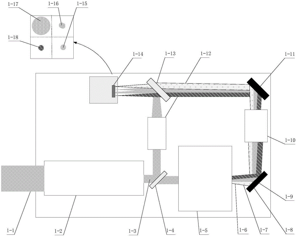
[0011] The technical problem to be solved by the present invention is: for the dual-beam combining sensor used as the pointing information of the detection beam in the two-way beam incoherent power combining system, by designing the optical path, using a single detector, using different detection areas, simultaneously performing single-way beam detection The imaging of far field, combined beam far field and beam combined near field can directly display the state of pupil and optical axis combined beam while ensuring that each beam can detect the error information of the optical axis independently; it not only reduces the detector’s It also ensures the consistency of the datum and the real-time and direct display of the state of the bundle

Method used


Image

  • Double-light-beam synthesis sensor by utilizing single detector to perform optical pupil and optical axis regional imaging
  • Double-light-beam synthesis sensor by utilizing single detector to perform optical pupil and optical axis regional imaging
  • Double-light-beam synthesis sensor by utilizing single detector to perform optical pupil and optical axis regional imaging

Examples


Embodiment Construction

[0031] The present invention will be further described below in conjunction with the accompanying drawings and specific embodiments.

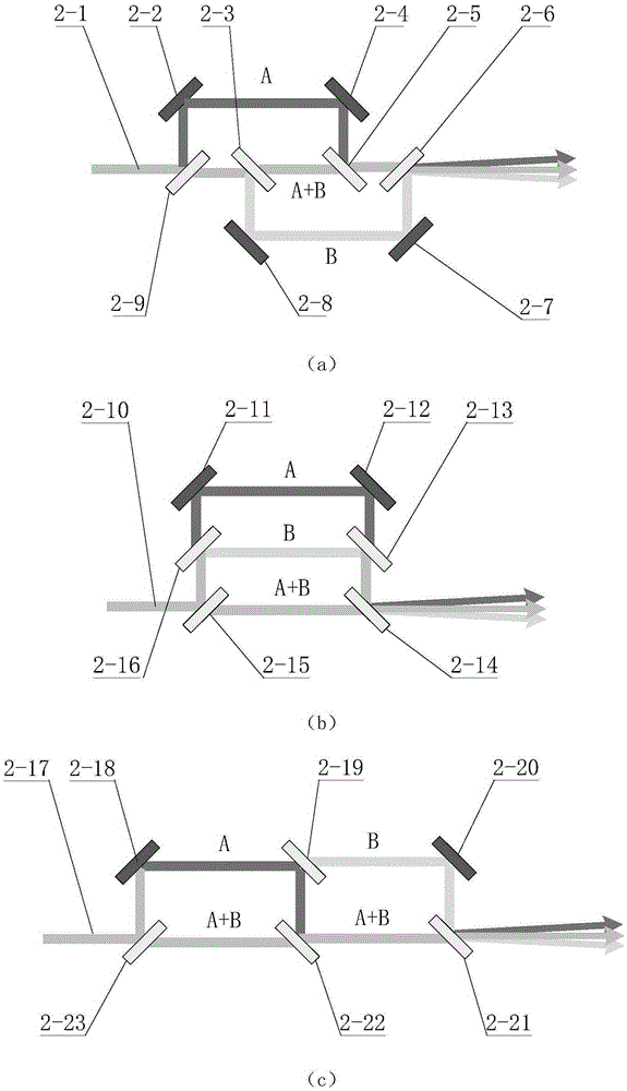
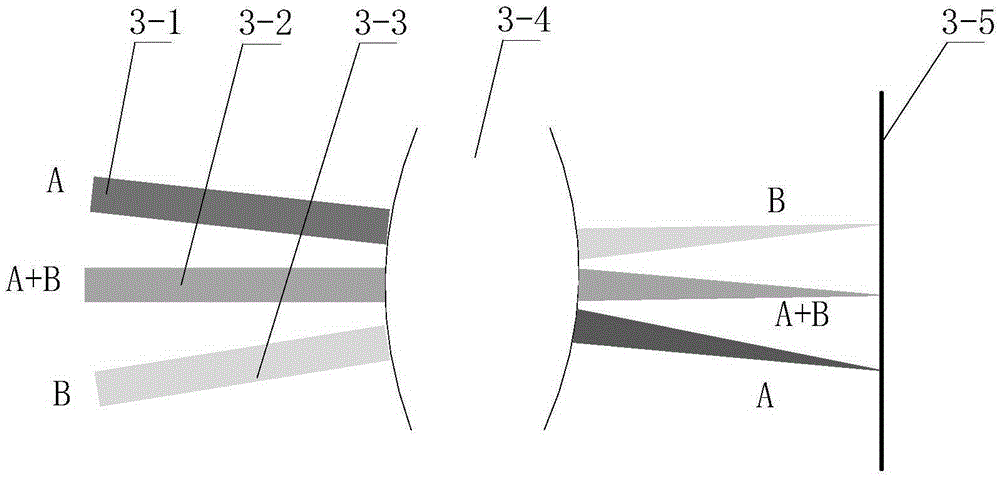
[0032] The principle of the present invention is as Figure 1 ~ Figure 3 shown. figure 1 is a schematic diagram of the optical path of the present invention, figure 2 is the internal typical structure of the optical axis separation module (1-5) of the present invention, image 3 is the schematic diagram of the focusing module (1-10).

[0033] Such as figure 1 As shown, the present invention consists of a common optical path shrinking module 1-2, a beam splitter 1-4, an optical axis separation module 1-5, an imaging module 1-12, a focusing module 1-10, a first coupling mirror 1-9, The second coupling mirror 1-11, the third coupling mirror 1-13 and the detector 1-14 are composed of several parts.

[0034] The functions performed by each part are: (1) The common optical path narrowing module 1-1 performs the function of narrowing the coinc...


PUM


Abstract

The invention discloses a double-light-beam synthesis sensor by utilizing a single detector to perform optical pupil and optical axis regional imaging. The double-light-beam synthesis sensor aims to solve the technical problem: when the power synthesis is performed aiming at two paths of laser beams having different wavelengths, the double-light-beam synthesis sensor is adopted to detect a near field (optical pupil information) and a far field (optical axis information) of the two paths of the light beams so that a synthesis condition of the two paths of the light beams is measured, calculated and analyzed; and, in the double-light-beam synthesis sensor, through adoption of a special optical-path structure, the optical pupil image and optical axis imaging of the two paths of the light beams can be simultaneously performed by utilizing the same detector. By utilizing the double-light-beam synthesis sensor, light beam directional error information of various paths of light beams can be detected in real time, the measuring structure can be simplified, usage of the detection can be reduced, the thermal drift problem brought by separate detection of multiple detectors can be eliminated, measurement consistency and stability are improved, and far field and near field synthesis conditions when the two paths of the light beams are synthesized can be analyzed in real time.

Description

technical field [0001] The invention relates to a dual-beam combining sensor and method for common-aperture power combining of two laser beams with different wavelengths, and belongs to the technical field of optical engineering. Background technique [0002] Beam combination is divided into coherent combination and non-coherent combination. Coherent or non-coherent combination can be carried out for multiple laser beams of the same wavelength; after coherent combination of N beams of the same power, the maximum beam energy density can be the original N 2 times, but it is very difficult to realize because the combined beams are required to have the characteristics of the same frequency, the same vibration direction and constant phase difference. N beams of the same power with different wavelengths are incoherently combined, that is, power combined. Although the energy density of the combined beam is only N times the original, since there is no need to control the phase of ea...

Claims


Application Information

Patent Timeline
Patent Type & Authority Applications(China)
IPC IPC(8): G02B27/10
CPCG02B27/1006
Inventor 董道爱任绍恒鲜浩李新阳甘永东王彩霞
Owner INST OF OPTICS & ELECTRONICS - CHINESE ACAD OF SCI
Learn More