
Calibration method for synthesizing far field through single detector to improve double-beam synthesis precision and pointing accuracy

A technology with single detector and synthetic precision, which is applied in the field of optical engineering, can solve problems such as unrealistic and large detector dimensions, and achieve the effects of ensuring identity, avoiding thermal drift, and ensuring closed-loop accuracy

Active Publication Date: 2016-02-17
INST OF OPTICS & ELECTRONICS - CHINESE ACAD OF SCI
View PDF6 Cites 13 Cited by
  • Summary
  • Abstract
  • Description
  • Claims
  • Application Information

AI Technical Summary

Problems solved by technology

Its disadvantage is that it is necessary to make an optical system with very high processing accuracy and debugging accuracy as the standard light source. Before each work, the detector needs to be transported to the standard light source for calibration. Due to the relatively large size of the detector, each calibration is very difficult. It is very unrealistic to transport it to the special optical system in front of the standard light source, so it is necessary to invent a new calibration method for beam synthesis accuracy and pointing accuracy

Method used


Image

  • Calibration method for synthesizing far field through single detector to improve double-beam synthesis precision and pointing accuracy
  • Calibration method for synthesizing far field through single detector to improve double-beam synthesis precision and pointing accuracy
  • Calibration method for synthesizing far field through single detector to improve double-beam synthesis precision and pointing accuracy

Examples


Embodiment Construction

[0026] The present invention will be described in detail below in conjunction with the accompanying drawings and specific embodiments.

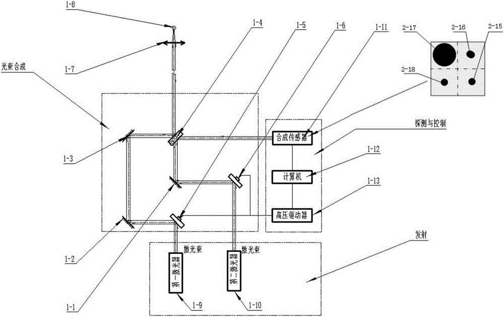
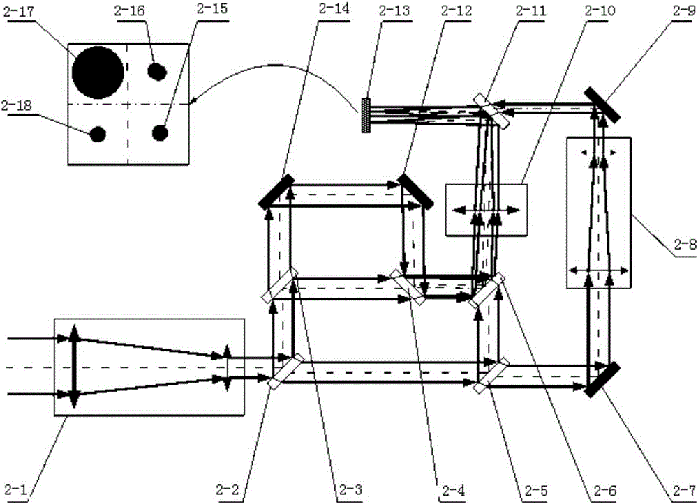
[0027] Such as figure 1 The first beam of light emitted by the first laser 1-9 shown passes through the first tunable mirror 1-1, the first transmission mirror 1-2, the second transmission mirror 1-3, and then synthesizes the beam-splitting and combining mirror 1-4. The second beam of light emitted by the second laser 1-10 passes through the second tunable mirror 1-5 and the third transmission mirror 1-6 and enters the composite beam-splitting mirror 1-4. Most of the energy of the first beam of light is reflected as the main beam through the composite beam-splitter mirror 1-4, and a very small part of the energy is transmitted into the composite sensor 1-11 through the composite beam-splitter mirror 1-4 as the measurement beam; the second beam of light Most of the energy is transmitted as the main beam through the composite beam-splitting mi...


PUM


Abstract

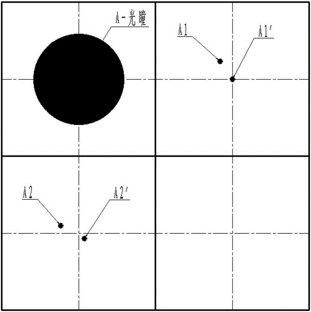
The invention discloses a calibration method for synthesizing a far field through a single detector to improve double-beam synthesis precision and pointing precision. According to the calibration method, the detection target surface of the same detector is subjected to area division, and four paths of measurement information are adjusted into four different areas which correspond to the real-time state information of a beam combination pupil, beam combination optical axes, a path A laser optical axis and a path B laser optical axis respectively. A path of laser and B path of laser are used for emitting light in the calibration process, the beam combination optical axes A1' and B1' are located on the absolute zero point of the center of the area in a closed loop mode, and after the coordinates of the beam combination optical axes A2' and B2' are respectively calculated, closed loop work is performed with the beam combination optical axes A2' and B2' as zero points. By means of the calibration method, calibration cost can be substantially reduced, a calibration structure is simplified, errors caused by equipment environment temperature and vibration are effectively eliminated, synthesis precision and stabilization precision of double beams on the target face of the detector are guaranteed, and therefore the synthesis precision and the pointing precision of output laser beams are improved.

Description

technical field [0001] The invention belongs to the technical field of optical engineering, and in particular relates to a calibration method for improving the synthesis accuracy and pointing accuracy of double beams by using a single detector to synthesize far fields. Background technique [0002] After combining N incoherent beams with different wavelengths, although the maximum energy density of the beam can only reach N times the original, but because it does not need to control the phase of each beam, it only needs to adjust and control the overall direction of each beam , so in engineering, we often combine N incoherent beams of different wavelengths, which is less technically difficult and easy to implement in work. In the patent No. ZL201210152113.4 (laser beam common aperture power combining system based on beam stable closed-loop control), the principle of using beam stable closed-loop control is proposed, and the beam combining sensor is used to extract the optica...

Claims


Application Information

Patent Timeline
IPC IPC(8): G01M11/02
CPCG01M11/02
Inventor 任绍恒甘永东王彩霞董道爱李建凤鲜浩李新阳李梅饶学军
Owner INST OF OPTICS & ELECTRONICS - CHINESE ACAD OF SCI
Learn More