
Automatic rapid clamping device for motor tests and use method of automatic rapid clamping device

A clamping device and motor testing technology, which is applied in the direction of motor generator testing, measuring devices, measuring device casings, etc., can solve the problems of high cost, complicated control, slow speed, etc., and achieve compact structure, small size and light weight Effect

Inactive Publication Date: 2016-02-24
昆山凯捷特电子研发科技有限公司
View PDF7 Cites 14 Cited by
  • Summary
  • Abstract
  • Description
  • Claims
  • Application Information

AI Technical Summary

Problems solved by technology

[0002] With the advent of the industry 4.0 era, the application of robots, robot arms, and motors is increasing day and night. At present, the motor test system basically uses screw locking for motor fixing. Because the motor shaft has a keyway instead of a perfect circular shaft, the motor shaft is assembled. There is a requirement for precise corners, and it is not easy to realize automation
At present, there are two types of existing assembly schemes. One type uses visual system recognition and automatic control. After visually identifying the angle of the shaft sleeve, it is necessary to control the motor to transfer to the corresponding angle before assembly can be carried out. This type The control of the scheme is complicated, the cost is high, and the speed is relatively high; the other kind of scheme is to manually rotate the motor shaft, which is slow and cannot realize automatic testing
The motors of these two types of schemes are fixed by semicircle clamping structure and screw locking structure. The semicircle clamping structure cannot be applied to the situation of motors of different sizes, and the efficiency of the screw locking structure is extremely slow.

Method used


Image

  • Automatic rapid clamping device for motor tests and use method of automatic rapid clamping device
  • Automatic rapid clamping device for motor tests and use method of automatic rapid clamping device
  • Automatic rapid clamping device for motor tests and use method of automatic rapid clamping device

Examples


Embodiment Construction

[0033] The present invention will be further described in detail below in conjunction with the accompanying drawings, so that those skilled in the art can implement it with reference to the description.

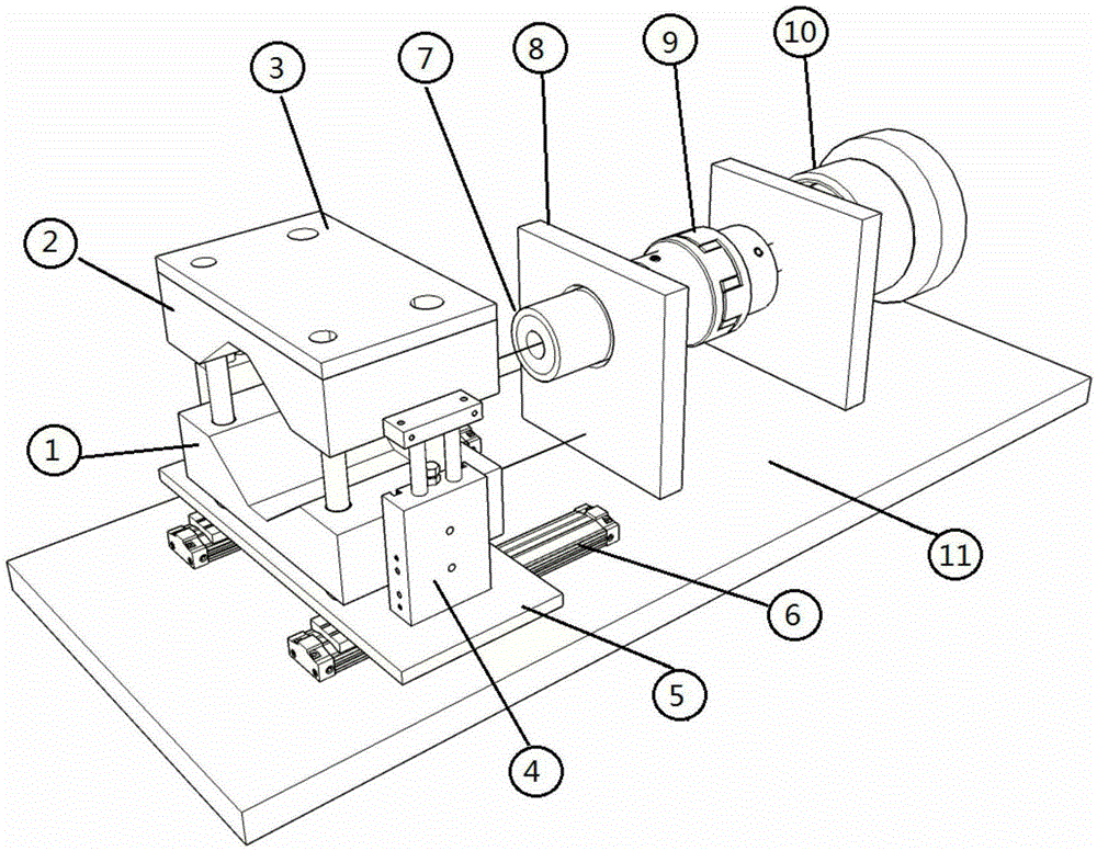
[0034] An automatic quick clamping device for motor testing, please refer to the attached Figure 1-3 , including: a base plate platform 11, and an adjustable motor fixing module and an arbitrary angle plug-in shaft connection structure arranged on the base plate platform,

[0035] Wherein, the adjustable motor fixing module includes a V-shaped locking block lower structure 1 for locking the motor, a V-shaped locking block upper structure 2, a locking block top plate 3, a clamping function cylinder 4, and an adjustable motor fixing module. Substrate 5, pneumatic sliding table guide rail 6; the clamping function cylinder pulls down the upper structure of the V-shaped lock block so that a clamping force is generated between the upper and lower structures of the V-shaped lock bl...


PUM


Abstract

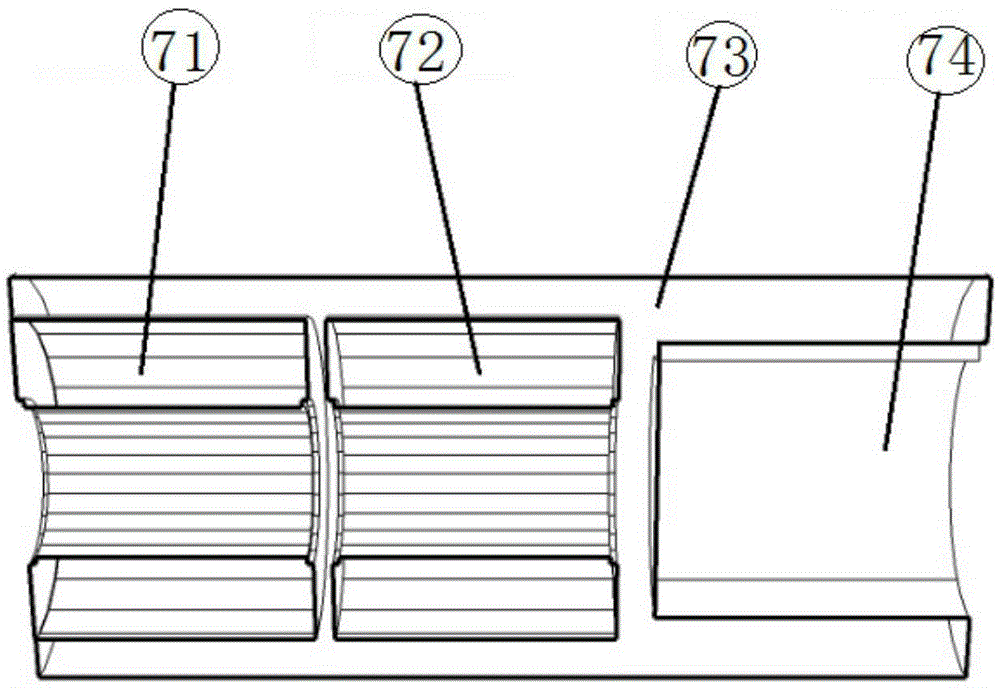
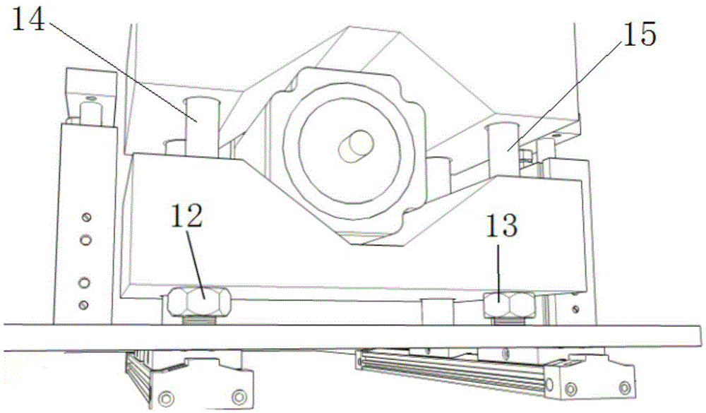
The invention relates to an automatic rapid clamping device for motor tests. The automatic rapid clamping device comprises a substrate platform as well as an adjustable motor fixing module and an arbitrary angle inserting shaft connecting structure which are arranged on the substrate platform, wherein the adjustable motor fixing module includes a V-shaped locking block lower structure and a V-shaped locking block upper structure which are used for locking a motor; the automatic rapid clamping device further comprises a locking block pushing plate, a pulling and clamping functional air cylinder, an adjustable motor fixing module substrate and pneumatic slide stage guide rails; the adjustable motor fixing module is provided with a guide column A and a guide column B which are vertical to the adjustable motor fixing module substrate; the arbitrary angle inserting shaft connecting structure includes an arbitrary angle inserting shaft connecting shaft, a bearing flange, a coupling and a load device, wherein the arbitrary angle inserting shaft connecting shaft is composed of a first one-way bearing, a second one-way bearing, a shaft sleeve and a keyway type shaft hole; the arbitrary angle inserting shaft connecting shaft is installed in the bearing of the bearing flange; one end of the arbitrary angle inserting shaft connecting shaft is assembled on the coupling, and therefore, the transmission of torque can be realized; and the coupling and the load device are fixed on the bearing flange.

Description

technical field [0001] The invention relates to a clamping device, in particular to an automatic fast clamping device for motor testing and a use method thereof. Background technique [0002] With the advent of the industry 4.0 era, the application of robots, robot arms, and motors is increasing day and night. At present, the motor test system basically uses screw locking for motor fixing. Because the motor shaft has a keyway instead of a perfect circular shaft, the motor shaft is assembled. There are requirements for precise corners, and it is not easy to realize automation. At present, there are two types of existing assembly schemes. One type uses visual system recognition and automatic control. After visually identifying the angle of the shaft sleeve, it is necessary to control the motor to transfer to the corresponding angle before assembly can be carried out. This type The control of the scheme is complicated, the cost is high, and the speed is relatively high; the ot...

Claims


Application Information

Patent Timeline
Patent Type & Authority Applications(China)
IPC IPC(8): G01R31/34G01R1/04
CPCG01R1/0425G01R31/34
Inventor 张明周桂刚陈守飞
Owner 昆山凯捷特电子研发科技有限公司
Learn More