Rigidity-variable spring type constant-flow valve

A variable stiffness spring, constant flow valve technology, applied in the field of hydraulic valves, can solve the problems of complex flow field, large flow resistance, small flow area, etc., and achieve the effect of large flow area, simple flow field and convenient installation.

Active Publication Date: 2016-02-24
JIANGSU MINGQUAN IRRIGATION & DRAINAGE EQUIP CO LTD
View PDF5 Cites 8 Cited by
  • Summary
  • Abstract
  • Description
  • Claims
  • Application Information

AI Technical Summary

Problems solved by technology

The structure of the published mechanical self-operated constant flow control valves tends to be consistent, and their common disadvantages are complex flow field, small flow area, and large flow resistance.

Method used


Image

  • Rigidity-variable spring type constant-flow valve
  • Rigidity-variable spring type constant-flow valve

Examples


Embodiment Construction

[0017] The following is a specific embodiment of the present invention, and the present invention will be further described in conjunction with the accompanying drawings.

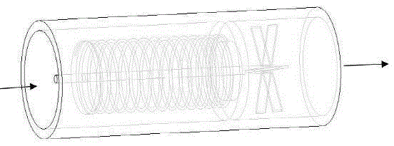
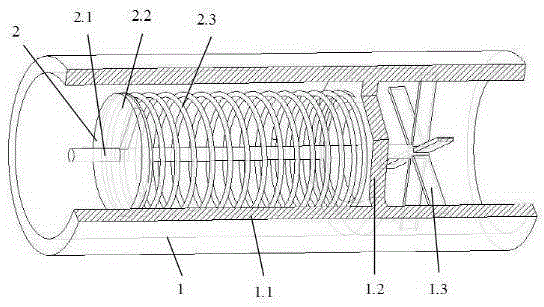
[0018] Such as figure 1 and figure 2 As shown, a variable stiffness spring type constant flow valve, the valve body 1 is mainly composed of a cylindrical shell 1.1, a retaining ring 1.2 and a fixed support 1.3 sequentially fixed in the shell 1.1. The spool 2 includes a guide rod 2.1 fixed on the fixed support 1.3, a baffle plate 2.2 that is installed on the guide rod 2.1 and can slide along the guide rod 2.1, and a variable stiffness spring 2.3 connected between the baffle plate 2.2 and the retaining ring 1.2. The retaining ring 1.2 is a circular plate with a circular hole in the center. The periphery of the retaining ring 1.2 is fixedly connected with the inner wall of the housing 1.1 to ensure sealing. The inner diameter of the retaining ring 1.2 is smaller than the diameter of the variable stiffness sp...


PUM


Abstract

The invention discloses a rigidity-variable spring type constant-flow valve and belongs to the technical field of hydraulic valves. The rigidity-variable spring type constant-flow valve comprises a valve body and a valve element arranged in the valve body. The valve body comprises a cylindrical shell. A baffle ring and a fixing support are sequentially fixed in the shell. The valve element comprises a guide rod fixed to the fixing support. The guide rod penetrates the center of the baffle ring and coincides with the axis of the shell. A baffle capable of sliding along the guide rod is arranged on the guide rod. A rigidity-variable spring is fixed between the baffle and the baffle ring. One end of the rigidity-variable spring is fixed to the baffle and the other end of the rigidity-variable spring is fixed to the baffle ring. When fluid of certain pressure passes seams of the spring, the pressure difference is generated, the pressure difference acts on the baffle at one end of the rigidity-variable spring, the rigidity-variable spring is compressed, the seam height of the rigidity-variable spring is changed, and certain flow is guaranteed. The rigidity-variable spring type constant-flow valve has the beneficial effects of being simple and reliable in structure, convenient to mount, simple in flow field, large in through-flow area, small in flow resistance and the like.

Description

technical field [0001] The invention relates to the technical field of hydraulic valves, in particular to a variable stiffness spring type constant flow valve. Background technique [0002] In water supply, filling, air conditioning and other systems, a large number of constant flow control valves are used to maintain the stability of flow. Constant flow control valves have been used in foreign countries for more than 30 years, but they have not been widely used in China, and there are few related researches. The mechanical self-operated constant flow control valve is a typical constant flow control valve, which is specially used in the fluid pipe network system that requires constant flow control. The structure of the published mechanical self-operated constant flow control valves tends to be consistent, but their common disadvantages are complex flow field, small flow area, and large flow resistance. [0003] With the development of modern production technology, the manu...

Claims


Application Information

Patent Timeline
Patent Type & Authority Applications(China)
IPC IPC(8): F16K17/30
CPCF16K17/30
Inventor 黎少辉汤文成
Owner JIANGSU MINGQUAN IRRIGATION & DRAINAGE EQUIP CO LTD
Why Eureka
Try Eureka