
Thread self-locking combined anchor bolt

A combined and threaded technology, which is applied in the direction of connecting components, pins, mechanical equipment, etc., can solve the problems of anchor bolt safety influence, weak fit, and anchor bolt lock not tight, etc.

Active Publication Date: 2016-02-24
FUZHOU BAIYIBAILI AUTOMATION TECH CO LTD
View PDF12 Cites 0 Cited by
  • Summary
  • Abstract
  • Description
  • Claims
  • Application Information

AI Technical Summary

Problems solved by technology

In actual use, it often occurs that the expansion ring and the extrusion cylinder liner are not tightly matched with the screw, which leads to the phenomenon that the anchor bolt is not locked tightly due to sliding, or the anchor bolt is easy to loose after multiple disassembly, resulting in The security of the anchor is compromised

Method used


Image

  • Thread self-locking combined anchor bolt
  • Thread self-locking combined anchor bolt
  • Thread self-locking combined anchor bolt

Examples


no. 1 example

[0035] First embodiment (the inner end of the inner rod 10 is provided with an eccentric countersunk 31):

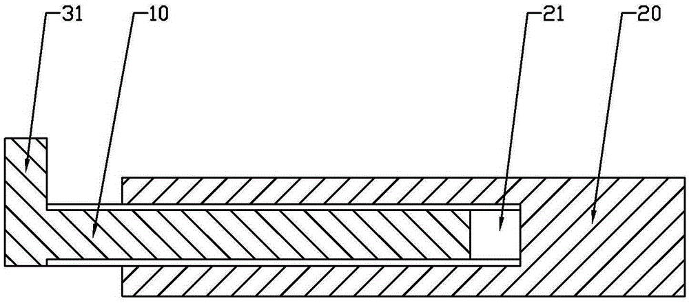
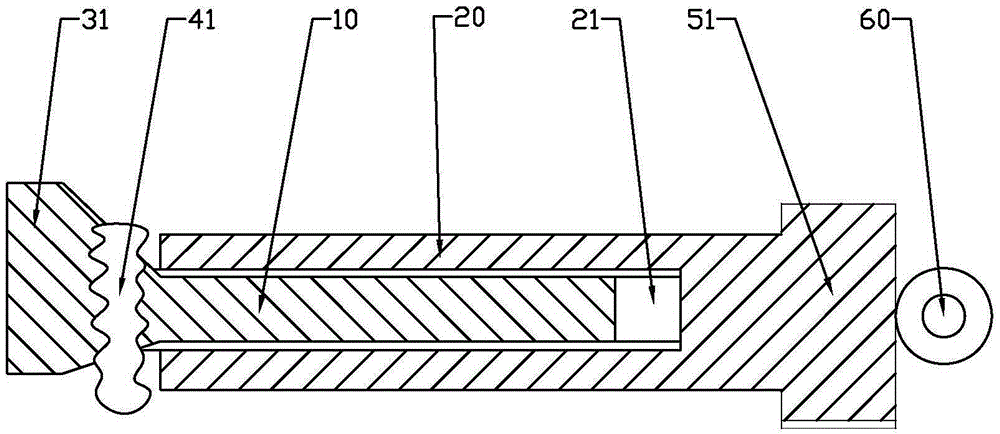
[0036] Such as figure 1 As shown, a threaded self-locking combined anchor bolt of this embodiment includes an inner rod 10 and an outer rod 20, the body of the inner rod 10 is provided with an external thread segment, and the inner end of the inner rod 10 is provided with Countersunk head, the rod body of the outer rod 20 is provided with a threaded inner hole 21, and the threaded inner hole 21 is provided with an inner threaded section matching the outer threaded section of the inner rod 10, and the outer end of the outer rod 20 is provided with The screw part for screw operation, in this embodiment, the countersunk head is an eccentric countersunk head 31, and the eccentric part 31 of the eccentric countersunk head 31 protrudes out of the outer rod 20, and is set in the anchor hole to be anchored in line with the The eccentric countersunk 31 matches the radial slot, a...

no. 6 example

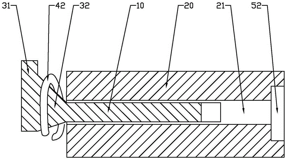
[0046] The sixth embodiment (the inner end of the outer rod 20 is provided with an integrally formed expansion sleeve 43):

[0047] Such as Figure 6 As shown, the difference from the fifth embodiment is that in this embodiment, the expansion sleeve 43 is integrally formed on the inner end of the outer rod 20, and an inner end is provided on the outer end of the outer rod 20. Concave screw port 52, by operating the screw port, the outer rod 20 is threadedly connected with the inner rod 10 and matched with the countersunk head to expand the expansion part and insert it into the anchor hole to be anchored for locking . When the outer rod 20 is screwed inward and squeezes the countersunk head of the inner rod 10, the expansion strip or the expansion sheet expands outward and embeds into the inner wall of the anchor hole to be anchored, thereby realizing the anchoring effect.

[0048] In each of the above-mentioned embodiments, the eccentric countersunk 31 can be provided separa...


PUM


Abstract

The invention discloses a thread self-locking combined anchor bolt. The thread self-locking combined anchor bolt comprises an inner rod and an outer rod; a rod body of the inner rod is provided with an outer screw thread section, and a countersunk head is disposed at the inner end of the inner rod; an inner threaded hole is formed in a rod body of the outer rod; the countersunk head is an eccentric countersunk head or a center countersunk head or a combined countersunk head of which the center part and the eccentric part are combined; the outer rod and the inner rod are made to be in threaded connection by operating the spiral part of the outer end of the outer rod, so that the eccentric countersunk head is embedded into a to-be-anchored anchor hole for locking, or the center countersunk head cooperates with an expanding part between the inner ends of the outer rod to cause expansion and to be embedded into the to-be-anchored anchor hole, or the center part of the combined countersunk head cooperates with the expanding part between the inner ends of the outer rod to cause expansion and to be embedded into the to-be-anchored anchor hole, and the eccentric part of the combined countersunk head is embedded into the to-be-anchored anchor hole for double locking; accordingly, the anchoring function is achieved, actual effect cannot be achieved even after repeatedly dismantling, the service life is longer, and the safety performance is higher.

Description

technical field [0001] The invention relates to an anchoring technology, in particular to a threaded self-locking combined anchor bolt. Background technique [0002] At present, percussion anchor bolts are commonly used in construction in the field of building decoration, which are usually composed of screw rods, expansion rings, extruded steel sleeves, gaskets and nuts. On the screw, the expansion ring can expand into a wedge shape on the expansion end of the screw, and then insert the expansion end of the screw, the expansion ring and the extrusion cylinder liner into the preset installation hole on the back of the stone plate, and then use the external sleeve And the hammer is knocked, and the expansion ring is stretched by the expansion end of the screw, so that the expansion end of the screw is consolidated with the bottom of the matching installation hole, and the cylindrical extruded cylinder liner is placed in the cylindrical hole. Like this, gasket and nut are inst...

Claims


Application Information

Patent Timeline
Patent Type & Authority Applications(China)
IPC IPC(8): F16B13/10
CPCF16B13/04F16B13/10
Inventor 李诗全
Owner FUZHOU BAIYIBAILI AUTOMATION TECH CO LTD
Learn More