Advanced pre-grouting device suitable for shallow-buried tunnel construction in sand soil layer and construction process

A technology for shallow-buried tunnels and sandy soil layers, which is applied in the field of advanced pre-grouting devices and construction techniques for shallow-buried tunnels in sandy soil layers. cumbersome and other problems, to achieve the effect of simple grouting device and process, high rigidity, and simple structure of grouting device

Inactive Publication Date: 2016-02-24
SHANDONG UNIV
View PDF5 Cites 19 Cited by
  • Summary
  • Abstract
  • Description
  • Claims
  • Application Information

AI Technical Summary

Problems solved by technology

Sleeve valve grouting can achieve uniform reinforcement of strata at different depths, but it has many and complicated procedures, cumbersome operation process, long construction period, and high cost; advancing open hole grouting process is relatively simple and easy to operate, but it cannot achieve Strengthen grouting in fixed-point areas. When the grouting hole is long, the grout cannot be spread evenly along the entire length of the hole, and the grouting effect is poor; the grouting of the mold bag grouting pipe focuses on the fixing and sealing effect of the grouting pipe. It is impossible to ensure that the ground is fully and uniformly reinforced and that the surface uplift does not exceed the specified value at the same time.

Method used


Image

  • Advanced pre-grouting device suitable for shallow-buried tunnel construction in sand soil layer and construction process
  • Advanced pre-grouting device suitable for shallow-buried tunnel construction in sand soil layer and construction process
  • Advanced pre-grouting device suitable for shallow-buried tunnel construction in sand soil layer and construction process

Examples


Embodiment Construction

[0035] The present invention will be further described below in conjunction with the accompanying drawings and embodiments.

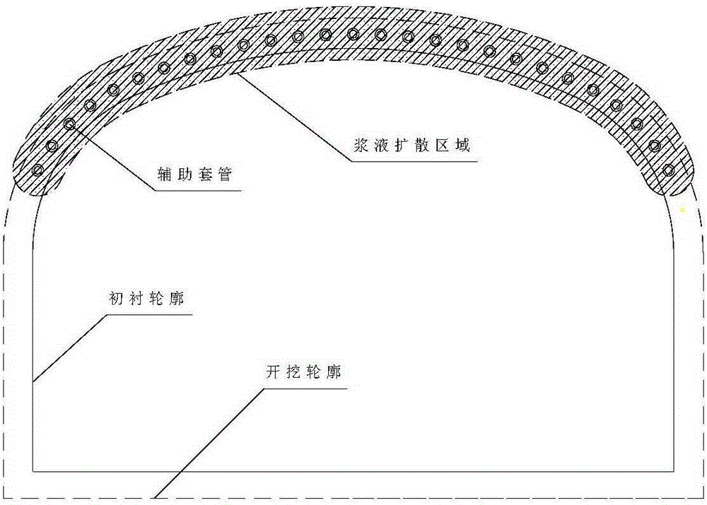
[0036] An advanced pre-grouting device suitable for shallow buried tunnels in sandy soil layers, such as figure 1 As shown, it is mainly composed of an auxiliary casing and a grouting inner pipe. The auxiliary casing includes a thickened steel pipe 4, a grout stopper cap 10, a one-way grouting hole 3, a tail flange 2, and a sealing flange 1. The grouting inner The pipe includes a steel pipe 7, a through valve 6, a flange 8, a rubber piston 9, and a slurry outlet 5.

[0037] The auxiliary casing is set on the outer layer of the grouting inner pipe; the head of the auxiliary casing is installed with a grout stop cap 10, and the middle part is arranged with a one-way grouting hole 3 to prevent the backflow of the grout; the grouting inner pipe and the auxiliary casing There are two rubber pistons 9 and two flanges 8 between the sleeves, the rubber pistons...


PUM


Abstract

The invention discloses an advanced pre-grouting device suitable for shallow-buried tunnel construction in a sand soil layer and a construction process. The advanced pre-grouting device comprises an auxiliary casing pipe and a grouting inner pipe. The grouting inner pipe is sleeved with two rubber pistons. Two flanges are welded to the grouting inner pipe. Slurry outlet holes are distributed between the two rubber pistons. Grouting and reinforcing conducted on strata of different depths are achieved by moving the grouting inner pipe in the auxiliary casing pipe. One-way slurry outlet holes are formed in the auxiliary casing pipe and can effectively prevent slurry from flowing back. After grouting is completed, the auxiliary casing pipe forms a curtain together with slurry veins by serving as a supporting framework. According to the advanced pre-grouting device and the construction process, segmented and domain-controlled grouting is achieved through movement of the grouting inner pipe, it is ensured that the strata are evenly reinforced, no blind points are generated, and disasters are avoided; slurry is effectively utilized; meanwhile, influences on the overlying strata and the ground surface are reduced, and damage to underground pipelines, ground surface road surfaces and above-ground buildings is prevented; and the auxiliary casing pipe is left in the strata and plays a role of a high-strength beam, slurry is dispersed around the auxiliary casing pipe, and a soil body and the auxiliary casting pipe can form the whole curtain.

Description

technical field [0001] The invention belongs to the field of geotechnical engineering, and in particular relates to an advanced pre-grouting device and construction technology suitable for shallow tunnels buried in sandy soil layers. Background technique [0002] Construction of shallow tunnels in soft sandy soil often results in stratum loss or even collapse due to excavation, which endangers the safety of construction personnel and equipment, and the excessive surface subsidence caused by stratum loss causes damage to the surrounding environment and brings great harm to residents. Normal production and life have been seriously affected. In order to ensure construction safety and reduce the impact of construction on the environment, the grouting reinforcement method is often used at home and abroad to pre-reinforce the ground. [0003] In traditional grouting reinforcement and water blocking, the diffusion of grout in the sand layer is mainly splitting, which is random and...

Claims


Application Information

Patent Timeline
IPC IPC(8): E02D3/12E02D15/04
CPCE02D3/12E02D15/04E02D2250/003E21D9/001
Inventor 刘人太张世杰张连震刘建国姜鹏王洪波程冰川
Owner SHANDONG UNIV
Why Eureka
Try Eureka