Cladding method for inner hole of stand column
A column and inner hole technology, applied in the direction of metal material coating process and coating, can solve the problems of limited inner space of column inner hole and hinder the industrial application of laser technology, so as to improve operability, reduce friction coefficient, prevent The effect of cracking and deformation
- Summary
- Abstract
- Description
- Claims
- Application Information
AI Technical Summary
Problems solved by technology
Method used
Image

Examples
Embodiment 1
[0045] A cladding method for an inner hole of a column, comprising the following steps:
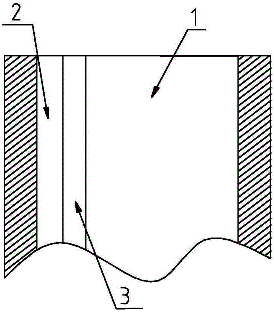
[0046] (1) pretreat the inner hole of the column 1 to be processed, remove the burrs and rust on the surface of the inner hole, and expose the metallic luster;
[0047] (2) Fix the column 1 to be processed on the tooling, place the laser head inside the column 1 to be processed, and the laser head moves in the direction of the main axis of the column 1 to be processed, and the laser head is provided with a smoke removal The device and powder feeding device can absorb the smoke generated during the cladding process in time;
[0048] (3) Adopt synchronous powder feeding mode, the laser head moves from one end of the column to be processed 1 to the other end along the main axis direction of the column to be processed 1, and completes a feed movement;
[0049] (4) The laser head resets along the main axis direction of the column 1 to be processed, and performs the next feed movement;
[005...
Embodiment 2
[0061] The same part of this embodiment and Embodiment 1 will not be described again, the difference is:
[0062] The alloy powder includes the following formula components: C: 0.06 parts, Mo: 14 parts, W: 5.0 parts, Ni: 36.5 parts, Fe: 5 parts, Mn: 0.7 parts, Cr: 13 parts, Si: 0.3 parts, V: 0.5 parts.
[0063] The length of the column 1 to be processed is 3m, and the cross section of the column 1 to be processed is a square, and the cladding method is as follows:
[0064] (1) During a feed movement of the laser head along the main axis direction of the column 1 to be processed, the laser head is clad from one end of the inner hole of the column 1 to be processed to the other end to obtain the Nth cladding strip 2 , the thickness of one side is 1.6mm;
[0065] (2) The laser head is reset along the main axis direction of the column 1 to be processed, and on the side of the Nth cladding strip 2, it is overlapped and clad from one end of the column 1 to be processed to the othe...
Embodiment 3
[0072] The same part of this embodiment and Embodiment 1 will not be described again, the difference is:
[0073] The alloy powder includes the following formula components: C: 0.08 parts, Mo: 16 parts, W: 5.5 parts, Ni: 43.9 parts, Fe: 7 parts, Mn: 1.0 parts, Cr: 15 parts, Si: 0.5 parts, V: 0.7 parts.
[0074] The length of the column 1 to be processed is 2.5m, and the cross section of the column 1 to be processed is a regular hexagon, and the cladding method is as follows:
[0075] (1) During a feed movement of the laser head along the main axis direction of the column 1 to be processed, the laser head is clad from one end of the inner hole of the column 1 to be processed to the other end to obtain the Nth cladding strip 2 , the thickness of one side is 2mm;
[0076] (2) The laser head is reset along the main axis direction of the column 1 to be processed, and on the side of the Nth cladding strip 2, it is overlapped and clad from one end of the column 1 to be processed to...
PUM
| Property | Measurement | Unit |
|---|---|---|
| thickness | aaaaa | aaaaa |
| hardness | aaaaa | aaaaa |
| hardness | aaaaa | aaaaa |
Abstract
Description
Claims
Application Information
 - R&D
- Intellectual Property
- Life Sciences
- Materials
- Tech Scout
- Unparalleled Data Quality
- Higher Quality Content
- 60% Fewer Hallucinations
Browse by: Latest US Patents, China's latest patents, Technical Efficacy Thesaurus, Application Domain, Technology Topic, Popular Technical Reports.
© 2025 PatSnap. All rights reserved.Legal|Privacy policy|Modern Slavery Act Transparency Statement|Sitemap|About US| Contact US: help@patsnap.com