
Determination method for tyre and ground optimum brake slipping point

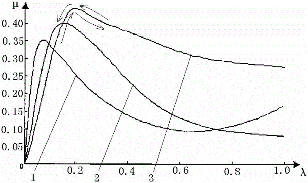
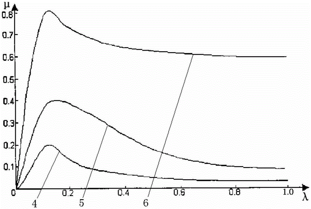
A determination method and technology of tires, applied in the direction of aircraft brake arrangement, brake regulator, etc., can solve problems such as difficult and accurate calculation and detection, and achieve the effect of great practical value

Active Publication Date: 2016-02-24
XIAN AVIATION BRAKE TECH
View PDF6 Cites 14 Cited by
  • Summary
  • Abstract
  • Description
  • Claims
  • Application Information

AI Technical Summary

Problems solved by technology

[0020] In order to overcome the problems existing in the prior art that there is a large discrepancy between the work efficiency evaluation standard of the brake system and the objective reality, and it is difficult to realize accurate calculation and detection for the most rigorous work efficiency evaluation method, the present invention proposes a tire-to-ground optimal Determination method of brake slip point

Method used


Image

  • Determination method for tyre and ground optimum brake slipping point
  • Determination method for tyre and ground optimum brake slipping point
  • Determination method for tyre and ground optimum brake slipping point

Examples


Embodiment 1

[0060] This embodiment is the method for determining the optimum brake slip point on the surface of the tire and the drum when carrying out the dynamic brake anti-skid test of the brake system on the inertial platform. The specific process is:

[0061] Step 1, carry out the anti-skid brake test and record the test data:

[0062] Through the inertial test bench of the prior art, connect the aircraft wheel and the brake control system product to carry out the joint dynamic brake anti-skid test, record the change data and curve of each variable over time during the braking process, and the variables include braking torque, inertial platform, etc. The linear speed of the outer surface of the drum, the speed of the wheel and the rolling radius of the wheel.

[0063] Step 2, determine the moment of inertia and rotational acceleration of the wheel:

[0064] Through the conventional moment of inertia calculation formula. Determine the moments of inertia of all parts that rotate rand...

Embodiment 2

[0081] This embodiment is the method for determining the best brake slip point between the tire and the ground when carrying out the ground brake anti-skid performance test of the brake system on the aircraft. The specific process is:

[0082] Step 1, conduct anti-skid brake test and record test data

[0083] According to the test requirements of the test program, the system anti-skid test is carried out through ground taxiing brakes on the aircraft, and the data and curves of various variables during the braking process are recorded by sensors. Radial load, wheel angular velocity, wheel rolling radius and braking distance.

[0084] Step 2, determine the moment of inertia and rotational acceleration of the wheel:

[0085] Through the conventional moment of inertia calculation formula. Determine the moments of inertia of all parts that rotate randomly, and convert them into moments of inertia about the wheel shaft according to the transmission ratio; the parts include wheel a...


PUM


Abstract

Provided is a determination method for a tyre and ground optimum brake slipping point. An optimum brake slipping point of a tyre and the ground is determined during the brake process through the method, the combination coefficient of the optimum brake slipping point is calculated, calculation of a distance efficiency and a combination coefficient utilization rate of a brake system can be carried out according to test data detected in brake tests and according to requirements of standards, and the working efficiency of the brake system can be evaluated accurately. Through the method, an ideal curve of a brake resistance, a combination moment and a combination coefficient can be obtained in a 100% working efficiency condition, the resistance efficiency, the distance efficiency and the combination coefficient utilization rate of the brake system are calculated according to the ideal curve, and the working efficiency of the brake system is evaluated accurately.

Description

technical field [0001] The invention relates to the field of wheel brake system control, in particular to a method for determining the best brake slip point between tires and the ground, which is used for evaluating the working efficiency of the anti-skid brake system. Background technique [0002] In order to shorten the braking distance, improve work efficiency, ensure the control ability of the driving direction and the braking safety of the aircraft, most of the braking systems of common cars or aircraft are equipped with anti-skid control systems. The anti-skid braking system of aircraft is mainly controlled by brake command sensors and brakes The anti-skid brake system is composed of a device (comprehensively complete the brake control and anti-skid control functions), hydraulic servo valve, brake device, wheel, wheel speed sensor, etc. The structural principle of the anti-skid brake system is shown in figure 1 . [0003] The brake command sensor is installed in the c...

Claims


Application Information

Patent Timeline
IPC IPC(8): B64C25/46
CPCB64C25/46
Inventor 张谦
Owner XIAN AVIATION BRAKE TECH
Learn More