An electronic relay remote control circuit and method

A remote control, relay technology, applied in circuit devices, electrical components, etc., can solve the problems of manual reset and manual stop functions are difficult to achieve

Active Publication Date: 2018-04-24
JIANGSU DAQO KFINE ELECTRIC
View PDF4 Cites 0 Cited by
  • Summary
  • Abstract
  • Description
  • Claims
  • Application Information

AI Technical Summary

Problems solved by technology

If there is a situation where manual reset or manual stop is required, but the operator cannot arrive at the scene immediately, or the relay is used in a harsh environment that is difficult for people to access, the above manual reset and manual stop functions are difficult to achieve

Method used


Image

  • An electronic relay remote control circuit and method
  • An electronic relay remote control circuit and method
  • An electronic relay remote control circuit and method

Examples


Embodiment Construction

[0018] The present invention will be further described in detail below in conjunction with the drawings.

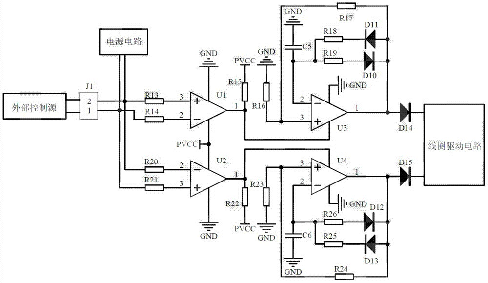
[0019] Such as figure 1 As shown, the present invention provides an electronic relay remote control circuit, which includes terminal J1, resistors R13, R14, R15, R16, R17, R18, R19, R20, R21, R22, R23, R24, R25, R26, Diodes D10, D11, D12, D13, D14, D15, capacitors C5, C6, comparators U1, U2, operational amplifiers U3, U4, power supply circuit, coil drive circuit;

[0020] One end of the connecting terminal J1 is connected to the resistor R14 and the resistor R21, the other end of the connecting terminal J1 is connected to the resistor R13 and the resistor R20, the other end of the resistor R13 is connected to the same direction end of the comparator U1, and the other end of the resistor R14 is connected to the comparator U1 The power terminal and ground terminal of comparator U1 are connected to system power PVCC and system ground GND respectively. The output terminal of comp...


PUM


Abstract

The invention relates to a remote control circuit of an electronic type relay. The remote control circuit comprises a wiring terminal J1, resistors R13-R26, diodes D10-D15, capacitors C5 and C6, comparators U1 and U2, operational amplifiers U3 and U4, a power supply circuit, a coil driving circuit and an external control source; the peripheral external control source is a direct current voltage source, and the two connection directions of the wiring terminal J1 respectively represent a stop function and a reset function. The peripheral power supply circuit is connected with the two ends of the wiring terminal J1, a rectifier bridge is contained in the peripheral power supply circuit, the rectifier bridge has no requirement on the connection direction of a power supply, so as to provide a system power supply PVCC (Permanent Virtual Channel Connection) and a system ground GND (Ground). The peripheral coil driving circuit receives stop and reset control signals sent by the remote control circuit and drives a coil and a relay mechanism to complete movement, so as to achieve the stop function and the reset function; meanwhile, the remote control circuit has the interlock function, thereby reducing the possibility of malfunction.

Description

Technical field [0001] The invention relates to an electronic relay remote control circuit, in particular to a circuit breaker or an overload relay in a low-voltage power distribution system. Background technique [0002] Electronic overload relay is one of the longest used electronic devices in the field of electronic control. It has the advantages of low cost and convenient use. At present, electronic overload relays have been widely used in low-voltage control systems. In the well-known technology, electronic overload The reset function of the relay has manual mode and automatic mode. At the same time, under normal circumstances, the electronic overload relay will be equipped with an emergency stop button for manual stop. If there is a situation that requires manual reset or manual stop, but the operator cannot arrive at the site immediately, or the relay is used in a harsh environment that is difficult for people to access, the above manual reset and manual stop functions are...

Claims


Application Information

Patent Timeline
Patent Type & Authority Patents(China)
IPC IPC(8): H02J13/00
CPCH02J13/00
Inventor 戴玮王兴刚刘彬马云鹏戴罡潘春燕
Owner JIANGSU DAQO KFINE ELECTRIC
Why Eureka
Try Eureka