Multi-purpose combined valve used for solar water heater

A solar water heater and combined valve technology, which is applied to solar thermal power generation, solar thermal devices, heating devices, etc., can solve the problem of not knowing the water level of the solar water heater water tank, unable to realize falling water type water intake and top water type water intake, and unable to provide independent water supply. Tap water and other problems, to achieve the effect of compact structure, simplified operation and lower overall cost

Inactive Publication Date: 2016-02-17
刘其勇
View PDF1 Cites 0 Cited by
  • Summary
  • Abstract
  • Description
  • Claims
  • Application Information

AI Technical Summary

Problems solved by technology

The disadvantages of this multi-directional regulating valve are that one cannot provide a separate cold water channel, and cannot independently provide tap water; The water level in the medium, do you need to add water?
[0006] The solar water heaters in the prior art are equipped with water supply and water discharge control valves, whether they are split independent control valves or integrated multi-directional control valves, they cannot realize both falling water intake and top water intake at the same time. The respective advantages of the two water intake methods

Method used


Image

  • Multi-purpose combined valve used for solar water heater
  • Multi-purpose combined valve used for solar water heater

Examples


Embodiment 1

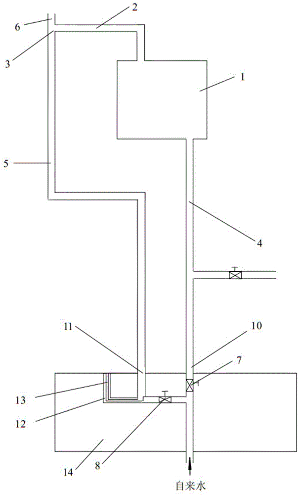
[0029] The multi-purpose combined valve used for solar water heaters of this embodiment has a structure as attached figure 1As shown, its composition includes a valve body 14 and a tap water inlet port arranged on the valve body, a water intake port, an overflow water port 11 connected to the water tank overflow pipe 5 and a downflow water port connected to the water tank downpipe 4 10. The intake water interface is connected with the tap water inlet interface, overflow water interface and downflow water interface through the flow channel. The flow channel after the confluence of the tap water inlet channel and the downflow water channel in the valve body is connected with the intake water outlet channel. The inlet water flow channel and the downflow water flow channel are the same straight flow channel, and are perpendicular to the confluence flow channel connecting the intake water outlet flow channel, forming a "T"-shaped structure; the overflow water flow channel is connect...

Embodiment 2

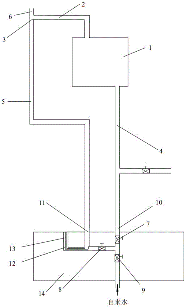
[0031] The structure of the multi-purpose combination valve used for solar water heaters in this embodiment is basically the same as that of the multi-purpose combination valve in Example 1, the difference is that an upper water regulating valve 9 is also arranged on the tap water inlet flow channel, and is arranged on The upper water regulating valve 9 on the tap water inlet flow path, the hot water regulating valve 7 arranged on the downflow flow path and the cold water regulating valve 8 arranged on the water outlet flow path share an adjustment handle. The multi-purpose combined valve of this embodiment is applicable to both the top water type and the falling water type for taking hot water.


PUM


Abstract

The invention provides a multi-purpose combined valve used for a solar water heater. The multi-purpose combined valve comprises a valve body, a tap water inlet connector arranged on the valve body, a water taking connector arranged on the valve body, an overflow water connector connected with a water tank overflow pipe, and a falling and flowing water connector connected with a water tank water falling pipe. The water taking connector is communicated with the tap water inlet connector, the overflow water connector and the falling and flowing water connector through channels. The tap water inlet connector is communicated with the falling and flowing water connector. A water feeding regulating valve is arranged on the tap water inlet channel. A hot water regulating valve is arranged on the falling and flowing water channel. A cold water regulating valve is arranged on the water taking and water discharging channel. By means of the multi-purpose combined valve used for the solar water heater, the water heater can have the water falling type water taking function and the water ejecting type water taking function at the same time, the advantages of the two water taking manners are brought into play, and control pipelines of the solar water heater are easy and fast to use, compact in structure, easy to install and operate and low in manufacturing cost.

Description

technical field [0001] The invention relates to an upper water control valve for a solar water heater, in particular to a multipurpose combined valve for upper water for a solar water heater. Background technique [0002] Solar water heaters are usually installed on outdoor roofs and connected to indoor water valves through pipes. Low frequency, less water volume, and higher temperature hot water are the characteristics of solar water heaters. The water stored in the pipeline between the hot water storage tank and the water valve, based on the heat loss in the natural state, often needs to be drained before use, wasting a lot of water. [0003] The hot water use of household solar water heaters can be divided into: 1. bathing water, 2. washing water, and 3. kitchen water; according to the temperature adjustment method, it can also be divided into: a synchronous temperature adjustment, b post temperature adjustment. For hot water applications with synchronous temperature ad...

Claims


Application Information

Patent Timeline
Patent Type & Authority Applications(China)
IPC IPC(8): F24J2/46
CPCY02E10/40
Inventor 刘其勇
Owner 刘其勇
Why Eureka
Try Eureka