
Speed reduction and pressure reduction device for vehicle engine and pressure reduction method

A technology of decompression device and engine, applied in the direction of engine components, engine control, machine/engine, etc., can solve the problems of reduced engine speed and short vehicle sliding distance, and achieve the trend of extending the sliding distance, extending the sliding distance, and slowing down the reduction. Effect

Active Publication Date: 2016-02-17
阮派烈
View PDF5 Cites 2 Cited by
  • Summary
  • Abstract
  • Description
  • Claims
  • Application Information

AI Technical Summary

Problems solved by technology

At this time, the speed of the engine will be dragged backward by the vehicle, and the speed of the engine will decrease with the speed of the vehicle. One end of the engine rocker arm contacts the engine valve. During this process, the valve opens and closes as the engine rocker rotates. When the valve is closed, the running resistance of the piston in the cylinder becomes larger, which makes the engine speed drop faster, resulting in a shorter gliding distance of the vehicle.

Method used


Image

  • Speed reduction and pressure reduction device for vehicle engine and pressure reduction method
  • Speed reduction and pressure reduction device for vehicle engine and pressure reduction method
  • Speed reduction and pressure reduction device for vehicle engine and pressure reduction method

Examples


Embodiment Construction

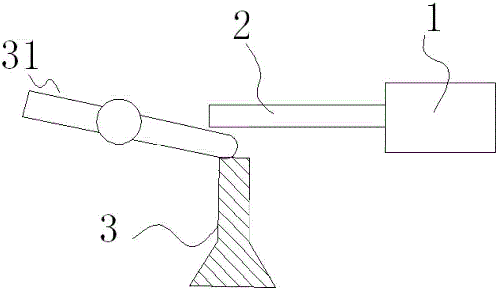
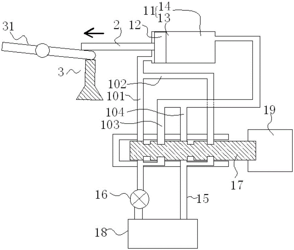
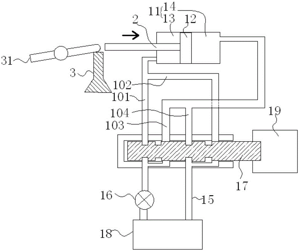
[0018] see Figure 1-3 , a vehicle engine deceleration and decompression device, including a drive mechanism 1 and a push rod 2, one end of the push rod 2 is fixed in the drive mechanism 1, and the other end of the push rod 2 is in contact with the engine valve when it is stretched out The upper end surface of the rocker arm 31; the drive mechanism 1 controls the telescopic movement of the push rod 2.

[0019] The driving mechanism 1 is a hydraulic mechanism. The hydraulic mechanism includes a hydraulic cylinder 11, the fixed end of the push rod 2 is arranged on the piston 12 in the hydraulic cylinder 11; the two ends of the piston 12 in the hydraulic cylinder 11 are respectively connected to the first oil circuit and a second oil circuit; the first oil circuit includes a first pressure oil circuit 101 and a first pressure relief oil circuit 102, and the second oil circuit includes a second pressure oil circuit 103 and a second pressure relief oil circuit 104; The first pres...


PUM


Abstract

The invention discloses a speed reduction and pressure reduction device for a vehicle engine and a pressure reduction method. The speed reduction and pressure reduction device comprises a driving mechanism and a push rod, wherein one end of the push rod is fixed to the driving mechanism. When the push rod extends out, the other end of the push rod abuts against the upper end surface of a rocker arm making contact with an engine valve. The driving mechanism controls the telescopic movement of the push rod. According to the speed reduction and pressure reduction device, when the engine is reversely towed by a vehicle in the advancing process of the vehicle, the operation resistance of an air cylinder piston of the engine is lowered, the lowering trend of the rotation speed of the engine is slowed down, and therefore the sliding distance of the vehicle in the process of reversely towing the engine to rotate is prolonged. According to a pressure reduction method during operation of the vehicle engine, an electronic control unit in the vehicle is utilized, the operation state of the vehicle is judged through information of sensors, and therefore pressure reduction can be carried out on the vehicle engine, the sliding distance of the vehicle in the process of reversely towing the engine to rotate in the set state is prolonged, and the practical value is high.

Description

technical field [0001] The invention relates to a vehicle engine deceleration and decompression device and a decompression method. Background technique [0002] When the vehicle accelerates to a certain speed, the engine speed must be higher than the engine speed when the engine is idling. At this time, if the driver releases the accelerator pedal, the fuel supply system in the engine will be in the state of idling, that is There is no human control of the fuel supply system or accelerator. At this time, the speed of the engine will be dragged backward by the vehicle, and the speed of the engine will decrease with the speed of the vehicle. One end of the engine rocker arm contacts the engine valve. During this process, the valve opens and closes as the engine rocker rotates. When the valve is closed, the running resistance of the piston in the cylinder becomes larger, which makes the engine speed drop faster, resulting in a shorter gliding distance of the vehicle. Content...

Claims


Application Information

Patent Timeline
Patent Type & Authority Applications(China)
IPC IPC(8): F01L9/02F02D13/02F01L9/10
CPCF02D13/02F01L9/10
Inventor 阮派烈
Owner 阮派烈
Learn More