Eureka AIR delivers breakthrough ideas for toughest innovation challenges, trusted by R&D personnel around the world.

Method and device for setting target wellhead pressures in control-pressure well drilling control systems

A target pressure and control system technology, which is applied to the automatic control system of drilling, wellbore/well valve devices, drilling equipment, etc., and can solve the problems of difficult or inaccurate control of wellhead pressure, wear, and setting jumps, etc.

Active Publication Date: 2016-02-17
XINJIANG GRAND OILFIELD TECH
View PDF9 Cites 14 Cited by
  • Summary
  • Abstract
  • Description
  • Claims
  • Application Information

AI Technical Summary

Problems solved by technology

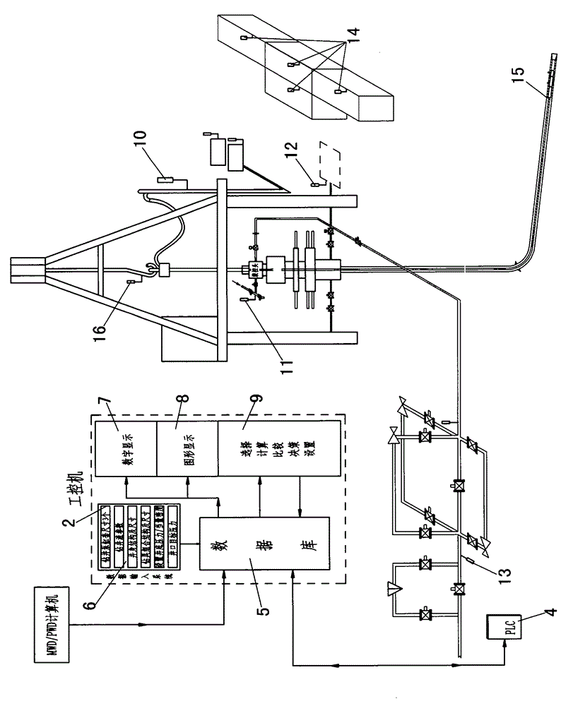
[0004] The purpose of the present invention is to provide a method and device for setting the wellhead target pressure in the managed pressure drilling control system, which can solve the problem of jumping and unstable setting of the wellhead target pressure of the drill bit at any depth of the wellbore, and difficult or inaccurate control of the wellhead pressure. The bottom hole pressure fluctuates greatly and is unstable, and the purpose of precise MPD cannot be implemented. At the same time, the throttle valve moves frequently, wears seriously, the control system is overloaded, and is easy to be damaged. Many unfavorable factors

Method used


Image

  • Method and device for setting target wellhead pressures in control-pressure well drilling control systems
  • Method and device for setting target wellhead pressures in control-pressure well drilling control systems

Examples


example 1

[0058] The well depth measured by the above components is 5,000 meters, the mud density is 1.2g / cm3, the wellhead pressure is 1 MPa, the pump displacement is 12 liters / second, the annular pressure consumption is 2 MPa, and the bottom hole setting pressure is 63Mpa.

[0059] The drill bit is at the bottom of the well: the wellhead setting pressure = the bottom hole setting pressure - the liquid column pressure below the drill bit - P1 + the wellhead pressure at that time;

[0060] Liquid column pressure below the drill bit=0 MPa (due to the drill bit at the bottom of the well);

[0061] P1=(Pn-n+...Pn-3+Pn-2+Pn-1) / n=(61.79+61.80+61.78+61.78+61.79) / 5=61.788MPa,

[0062] (Pn-n: must be between the liquid column pressure at the drill bit and the sum of liquid column pressure + maximum annular pressure loss + wellhead pressure, that is, between 58.8 MPa and 61.8 MPa, can be used for calculation, here: n=6, P1=61.79MPa, P2=61.80MPa, P3=61.78MPa, P4=61.78MPa, P5=69MPa, P6=61.79MPa; ...

example 2

[0067] The drill bit is measured at 3,000 meters by the above components: wellhead setting pressure = bottom hole setting pressure - liquid column pressure below the drill bit - P1 + wellhead pressure at that time;

[0068] Liquid column pressure below the drill bit = 1.2X0.0098X2000 = 23.52 MPa

[0069] P1=(Pn-n+...Pn-3+Pn-2+Pn-1) / n=(38.28+28.27+38.26+38.28+38.26) / 5=36.27MPa,

[0070] (Pn-n: must be between the liquid column pressure at the drill bit and the sum of liquid column pressure + maximum annular pressure loss + wellhead pressure, that is, between 35.28 MPa and 38.28 MPa, can be used for calculation, here: n=6, P1=38.28MPa, P2=38.27MPa, P3=38.26MPa, P4=38.28MPa, P5=45MPa, P6=38.26MPa; Note: P5=45MPa cannot participate in the calculation because it is not within the required pressure range )

[0071] At that time, the wellhead pressure was 1 MPa;

[0072] Wellhead setting pressure = 63 MPa - 23.52 MPa - 37.27 MPa + 1 = 4.21 MPa;

[0073] If the wellhead setting pr...


PUM


Abstract

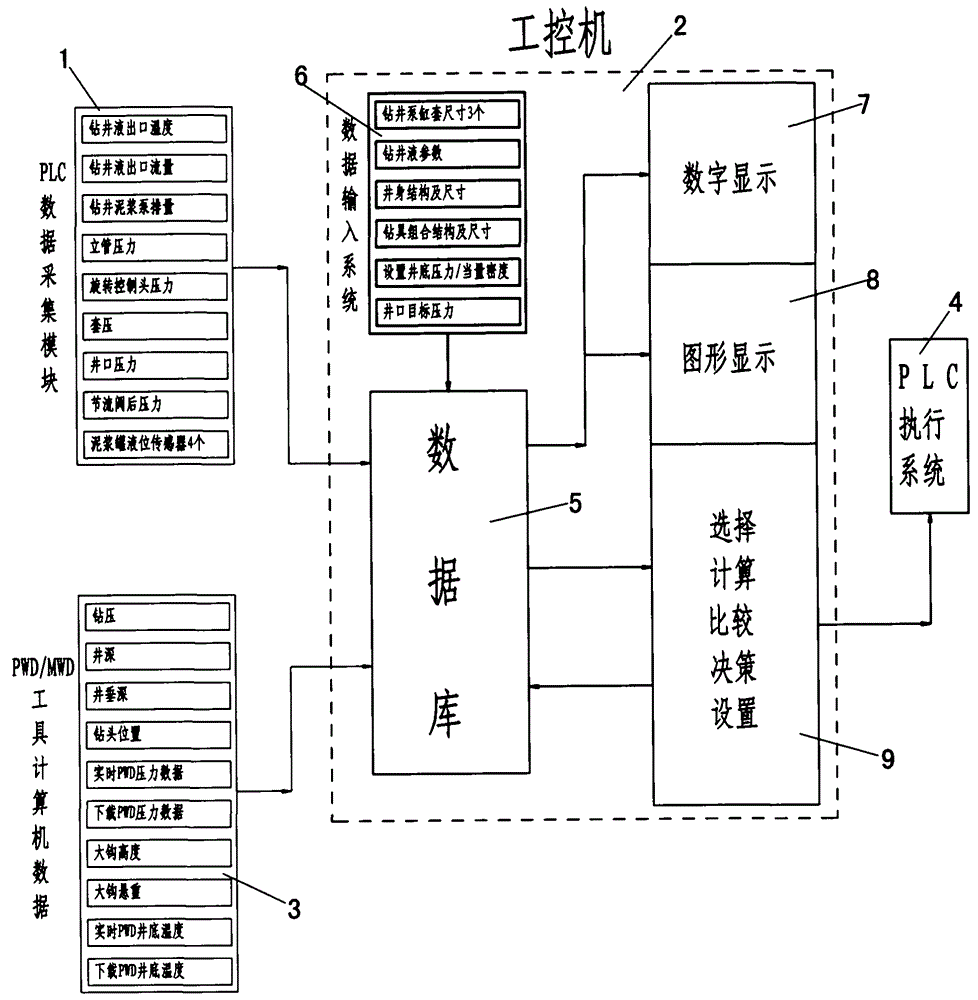
The invention discloses a method and a device for setting target wellhead pressures in control-pressure well drilling control systems. The method includes storing data of PWD while-drilling pressure measuring tools, control-pressure well drilling parameters acquired by PLCs (programmable logic controllers) in real time and various parameters of input systems of control systems of industrial personal computers into databases of the control-pressure well drilling control systems; setting ranges of PWD pressure data which participate in computation, computing average pressures by a plurality of selected PWD data to obtain a result P1, computing target wellhead pressures according to a formula of target wellhead pressures=set target bottom hole pressures-pressures of mud fluid columns below drill bits-P1+current wellhead pressures, setting the precision of the target wellhead pressures, keeping the original pressures if the target wellhead pressures are within difference value ranges, and utilizing the currently computed target wellhead pressures as the target wellhead pressures if the target wellhead pressures exceed the difference value ranges; enabling the industrial personal computers to transmit instructions to control systems of the PLCs to adjust the opening of throttle valves until actual wellhead pressures are close to the target wellhead pressures. The ranges of the PWD pressure data are higher than pressures of mud fluid columns above the drill bits and are lower than sums of pressures of fluid columns at the drill bits, pressure loss of annular spaces above the drill bits and wellhead pressures. The method and the device have the advantages that the target pressures can be stably and accurately set, and the control systems are easy to control.

Description

technical field [0001] The invention relates to a method and a device for setting a wellhead target pressure, in particular to a method and a device for setting a wellhead target pressure in a managed pressure drilling control system. Background technique [0002] In managed pressure drilling and underbalanced drilling, bottomhole pressure control is the key to complete drilling operations. The stable and accurate setting of wellhead target pressure is the basis for controlling wellhead pressure, and also the guarantee for realizing bottomhole pressure stability and precise control. [0003] At present, there are many methods for setting wellhead target pressure, and various control methods also have different setting methods, such as micro-flow control method, simulated bottomhole pressure calculation method, wellhead pressure calculation method for fine pressure control, etc. The first two methods There is no PWD pressure measurement tool in the downhole drilling tool asse...

Claims


Application Information

Patent Timeline
IPC IPC(8): E21B44/00E21B34/16
Inventor 贺志刚李雪刚李怀仲
Owner XINJIANG GRAND OILFIELD TECH
Why Eureka
Eureka Blog
Learn More