Flexible weight-reducing main girder structure of a crane
A technology for cranes and main girders, which is applied in the field of flexible weight-reducing main girder structures of cranes, which can solve the problems of large box-type main girders, inconvenient transportation and installation, and high quality, so as to achieve not easy to slide left and right, easy to transport, and reasonable structure Effect
- Summary
- Abstract
- Description
- Claims
- Application Information
AI Technical Summary
Problems solved by technology
Method used
Image

Examples
Embodiment 1
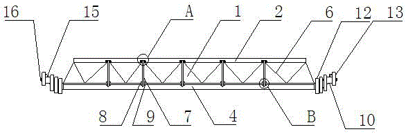
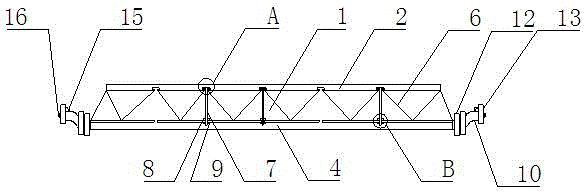
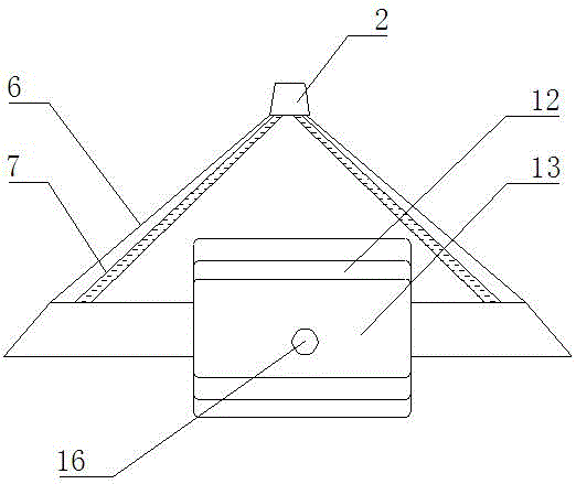
[0022] Such as Figure 1-7 As shown, a flexible weight-reducing main girder structure of a crane includes a main girder body 1, and the main girder body 1 includes an upper fixing rod 2 and a lower fixing plate 4, and the two sides of the upper fixing rod 2 are provided with Bolt groove 3, the both sides of described lower fixing plate 4 are provided with screw rod groove 5, between described upper fixing rod 2 and lower fixing plate 4, be evenly provided with oblique support bar 6, described bolt groove 3 and screw rod Bolts A7 are interspersed between the grooves 5, the upper nut 8 screwed on the bolt A7 is arranged above the screw groove 5, and the lower nut 8 screwed on the bolt A7 is arranged below the screw groove 5. Cap 9, the two ends of the lower fixing plate 4 are equipped with a flat hanging rod 10, the upper part of the end of the flat hanging rod 10 is provided with a groove 11, and a counterweight is placed on the flat hanging rod 10 12. The end of the flat hang...
Embodiment 2
[0025] Such as Figure 1-7 As shown, a flexible weight-reducing main girder structure of a crane includes a main girder body 1, and the main girder body 1 includes an upper fixing rod 2 and a lower fixing plate 4, and the two sides of the upper fixing rod 2 are provided with Bolt groove 3, the both sides of described lower fixing plate 4 are provided with screw rod groove 5, between described upper fixing rod 2 and lower fixing plate 4, be evenly provided with oblique support bar 6, described bolt groove 3 and screw rod Bolts A7 are interspersed between the grooves 5, the upper nut 8 screwed on the bolt A7 is arranged above the screw groove 5, and the lower nut 8 screwed on the bolt A7 is arranged below the screw groove 5. Cap 9, the two ends of the lower fixing plate 4 are equipped with a flat hanging rod 10, the upper part of the end of the flat hanging rod 10 is provided with a groove 11, and a counterweight is placed on the flat hanging rod 10 12. The end of the flat hang...
PUM
 Abstract
Description
Claims
Application Information
 - R&D
- Intellectual Property
- Life Sciences
- Materials
- Tech Scout
- Unparalleled Data Quality
- Higher Quality Content
- 60% Fewer Hallucinations
Browse by: Latest US Patents, China's latest patents, Technical Efficacy Thesaurus, Application Domain, Technology Topic, Popular Technical Reports.
© 2025 PatSnap. All rights reserved.Legal|Privacy policy|Modern Slavery Act Transparency Statement|Sitemap|About US| Contact US: help@patsnap.com