
Compression device for gas valve springs

A technology of air valve spring and compression device, which is applied in the field of machinery, can solve the problems of inconvenient carrying and use, flying out of air valve blocks and hurting people, and slipping of pressing tools, so as to achieve easy assembly, stable spring compression, and reduce The effect of installs

Active Publication Date: 2018-01-09
CHONGQING PUSH MECHANISM
View PDF5 Cites 0 Cited by
  • Summary
  • Abstract
  • Description
  • Claims
  • Application Information

AI Technical Summary

Problems solved by technology

The existing air valve spring pressing tool is not easy to disassemble, and there is a danger of the pressing tool slipping, causing the air valve block to fly out and hurt people. At the same time, because the same cylinder head is installed multiple times, the efficiency is low; the structure is complicated to carry and inconvenient to use

Method used


Image

  • Compression device for gas valve springs
  • Compression device for gas valve springs

Examples


Embodiment Construction

[0013] The present invention will be further described below in conjunction with the embodiments and accompanying drawings.

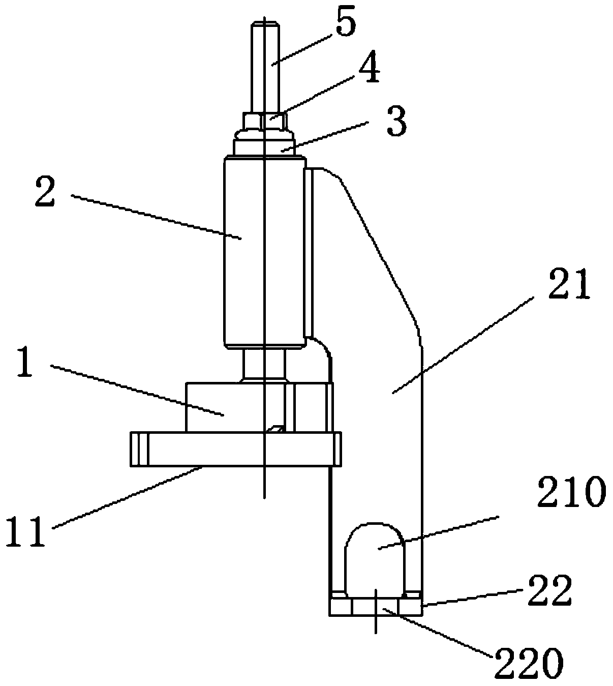
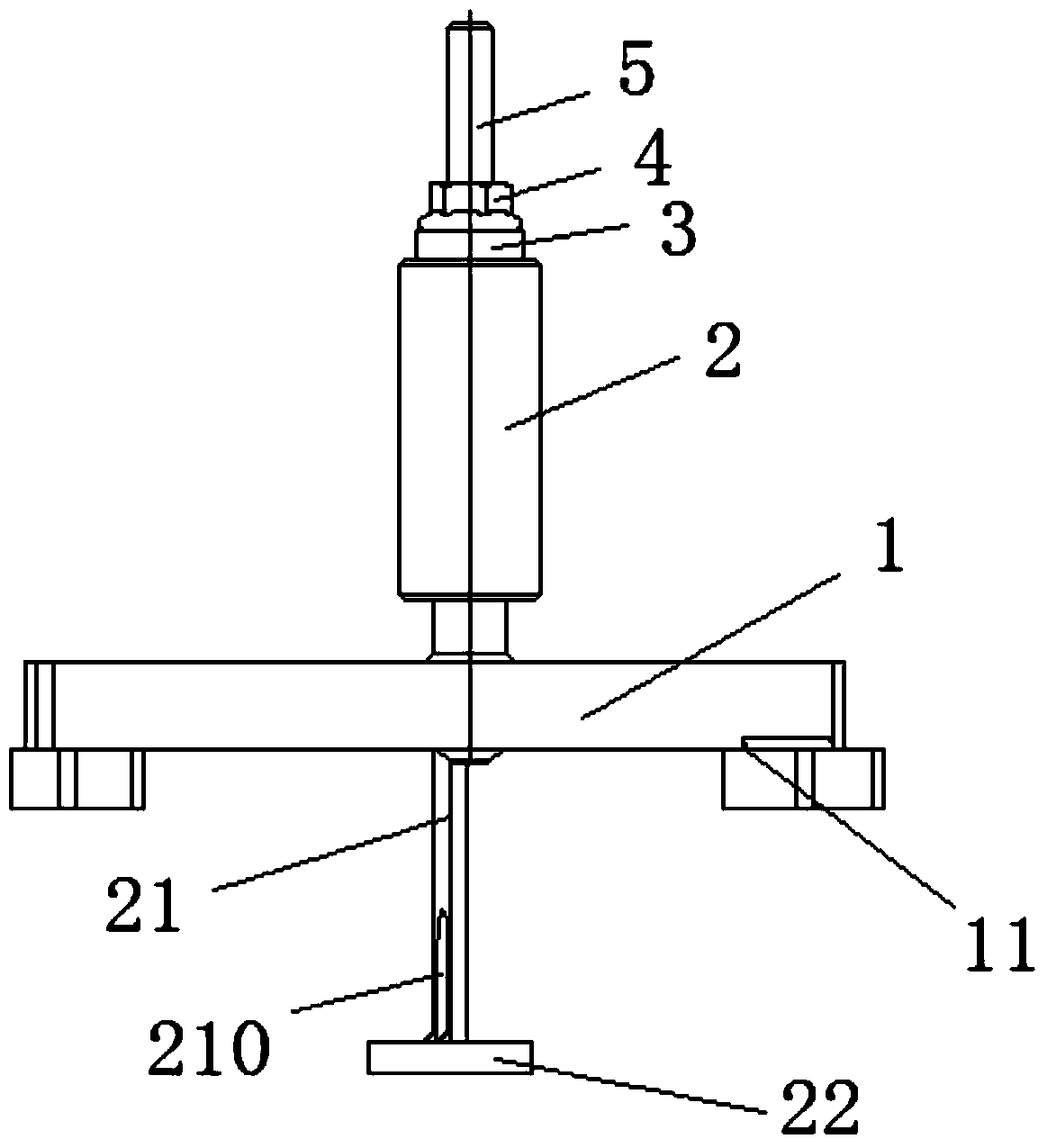
[0014] Such as figure 1 with figure 2 The shown pressing device for the air valve spring includes a stud 5, the lower end of which is provided with a rounded chamfer, which is convenient for installation, and the stud 5 is sequentially installed with a bracket 1, a stop Push column 2, washer 3 and nut 4, described support 1 is elongated, and is symmetrically distributed along the left and right sides of stud 5, and the bottom of this support 1 two ends is respectively provided with a fixed block 11, and nut is installed on this fixed block 11 .

[0015] The side of the thrust column 2 is provided with a rotating arm 21, the rotating arm 21 is in the shape of a half "C" and protrudes below the support 1, and an inverted U-shaped slot 210 is arranged below the rotating arm 21, and the U-shaped locking The lower end of the groove 210 is connected with ...


PUM


Abstract

The invention discloses a hold-down device for air valve spring. The hold-down device comprises a stud; a support, an anti-thrust column, a washer and a nut; a tumbler is arranged on a side surface of the anti-thrust column; an inverted U-shaped clamping groove is formed below the tumbler; a lower end of the tumbler is connected with a chuck; a through hole is formed in the center of the chuck. On the basis of an idea of rotation, during assembling, an angle of the anti-thrust column is rotated to change a position of mounting and demounting the air valve spring; due to a planar contact manner between the anti-thrust column and the air valve spring, the spring can be compressed steadily and controllable amount of compression of the spring can be guaranteed; the probability of elastic deformations caused by excessive compression of the spring can be reduced and a purpose of demounting a plurality of air values by mounting the tool once can be achieved, and furthermore, the mounting times of the tool are reduced.

Description

technical field [0001] The invention relates to a pressing device for an air valve spring, which belongs to the technical field of machinery. Background technique [0002] The air valve spring is installed in the air valve and plays a vital role in the working performance of the air valve. In actual work, it is often necessary to replace the air valve and the air valve spring, so it is ready to be pressed, disassembled and installed. The existing air valve spring pressing tool is not easy to disassemble, and there is a danger of the pressing tool slipping, causing the air valve block to fly out and hurt people. At the same time, because the same cylinder head is installed multiple times, the efficiency is low; the structure is complicated to carry And use is also inconvenient. Contents of the invention [0003] In view of this, the present invention provides a pressing device for air valve springs that is easy to carry, easy to operate, and easy to assemble. [0004] It...

Claims


Application Information

Patent Timeline
Patent Type & Authority Patents(China)
IPC IPC(8): B25B27/26
CPCB25B27/26
Inventor 赵亮彭勇亮李琳
Owner CHONGQING PUSH MECHANISM
Learn More