
Water faucet convenient to mount

A faucet, a convenient technology, applied in the field of faucets, can solve problems such as low production efficiency, high process requirements, and large labor investment, and achieve the effects of saving manpower and material resources, simplifying the installation process, and reducing errors and omissions

Inactive Publication Date: 2016-02-10
开平市华力水暖卫浴有限公司
View PDF0 Cites 0 Cited by
  • Summary
  • Abstract
  • Description
  • Claims
  • Application Information

AI Technical Summary

Problems solved by technology

[0002] At present, the internal passages of the faucets circulating in the market are relatively complicated, and complex pipelines require complex processes for production, so the faucets circulating in the market are all made of the internal components of the faucet using the sand-foundation process.
This process requires high gas, complicated operation, large labor input, high production cost and low production efficiency.
Moreover, the foundry process is not suitable for faucets made of plastic materials, and cannot be mass-produced quickly.

Method used


Image

  • Water faucet convenient to mount
  • Water faucet convenient to mount

Examples


Embodiment 1

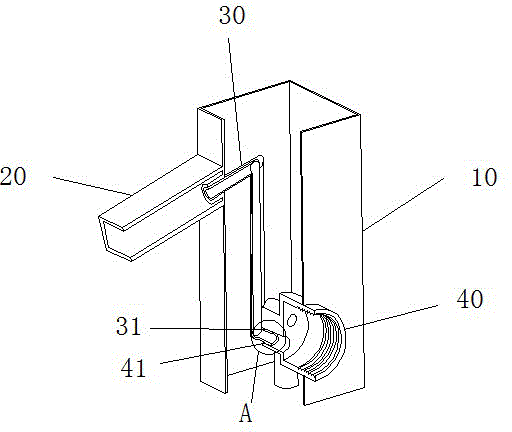
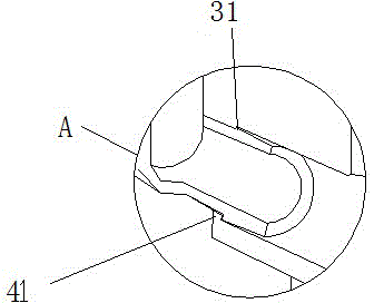
[0014] Such as figure 1 , 2 As shown, the conveniently installed water faucet of this embodiment includes an outer cavity 10, a drain port 20, a water outlet pipe 30 and a valve seat 40 arranged inside the outer chamber 10, and a convex rib 31 is provided at the joint between the water outlet pipe 30 and the valve seat 40. , the valve seat 40 is provided with a groove 41 at the junction of the water outlet pipe 30 . The length of the rib 31 is 10mm, and the depth of the groove 41 is 10mm. Both the valve seat (40) and the water outlet pipe (30) are made of plastic. When installing, squeeze the water outlet pipe 30 into the valve seat 40 until the convex rib 31 is firmly engaged with the groove 41, and then pull it outward until it is confirmed that the convex rib 31 and the groove 41 are tightly combined before installing other components. . The conveniently installed faucet of this embodiment adopts the core-pulling process and does not need to use the foundry process, so ...

Embodiment 2

[0016] Such as figure 1 , 2 As shown, the conveniently installed water faucet of this embodiment includes an outer cavity 10, a drain port 20, a water outlet pipe 30 and a valve seat 40 arranged inside the outer chamber 10, and a convex rib 31 is provided at the joint between the water outlet pipe 30 and the valve seat 40. , the valve seat 40 is provided with a groove 41 at the junction of the water outlet pipe 30 . Both the valve seat 40 and the water outlet pipe 30 are made of plastic. When installing, squeeze the water outlet pipe 30 into the valve seat 40 until the convex rib 31 is firmly engaged with the groove 41, and then pull it outward until it is confirmed that the convex rib 31 and the groove 41 are tightly combined before installing other components. . The conveniently installed faucet of this embodiment adopts the core-pulling process and does not need to use the foundry process, so it can save a lot of manpower and material resources, and reduce the production...


PUM


Abstract

The invention relates to a water faucet, in particular to a water faucet convenient to mount and applicable to various materials. The water faucet comprises an outer cavity, a drain opening, a water outlet pipe and a valve seat, wherein the water outlet pipe and the valve seat are arranged in the outer cavity. The joint of the water outlet pipe and the valve seat is provided with a flange, and the joint of the valve seat and the water outlet pipe is provided with a groove. The water faucet convenient to mount has the advantages that due to the fact that a core-pulling process is adopted, a great amount of manpower and material resources can be saved, and the production cost of an enterprise is reduced; plastic material is suitable for the water faucet manufactured through the core-pulling process, and the raw material cost of the water faucet is reduced, which benefits the enterprise; the water faucet is assembled through a buckle type structure, the mounting process becomes simple, operation is convenient, and mistakes and omissions in the mounting process are reduced.

Description

【Technical field】 [0001] The invention relates to a faucet, in particular to a faucet which is easy to install and is applicable to various materials. 【Background technique】 [0002] At present, the internal passages of the faucets circulating in the market are relatively complicated, and complex pipelines require complex processes for production, so the faucets circulating in the market are all made of the internal components of the faucet using the sand-foundation process. This process requires high gas, complicated operation, large labor input, high production cost and low production efficiency. Moreover, the foundry process is not suitable for faucets made of plastic, and cannot be mass-produced quickly. 【Content of invention】 [0003] The present invention aims to solve the above problems and provide a conveniently installed faucet which is suitable for various materials and is easy to install. [0004] In order to achieve the above purpose, the present inventio...

Claims


Application Information

Patent Timeline
Patent Type & Authority Applications(China)
IPC IPC(8): F16K27/00
Inventor 陈海燕
Owner 开平市华力水暖卫浴有限公司
Learn More