
Method and system for diagonal blow-through exhaust gas scavenging

A diagonal, exhaust valve technology, applied in electrical control, machine/engine, output power, etc., can solve problems such as increasing the amount of boosted air, limiting the amount of boosting, etc., to reduce excess heating, improve fuel economy, The effect of reducing the incidence of knocking

Active Publication Date: 2016-02-10
FORD GLOBAL TECH LLC
View PDF5 Cites 6 Cited by
  • Summary
  • Abstract
  • Description
  • Claims
  • Application Information

AI Technical Summary

Problems solved by technology

Therefore, an increased amount of boost air may be required to clear the discharge chamber, which may limit the amount of boost that can be provided by the compressor

Method used


Image

  • Method and system for diagonal blow-through exhaust gas scavenging
  • Method and system for diagonal blow-through exhaust gas scavenging
  • Method and system for diagonal blow-through exhaust gas scavenging

Examples


Embodiment Construction

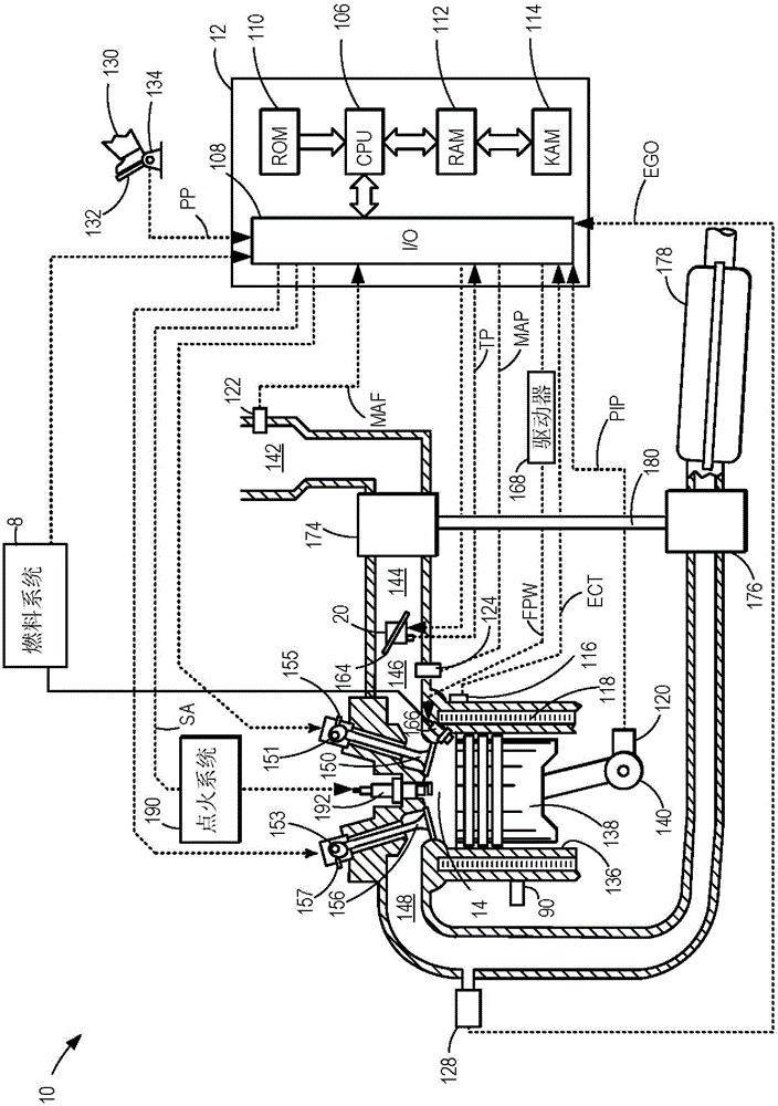
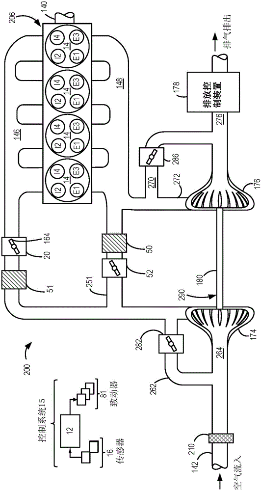
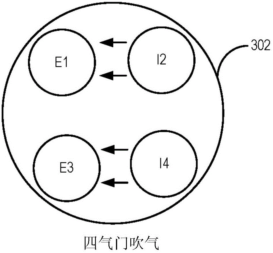
[0020] This instruction manual refers to the Figure 1-2 Methods and systems for improving scavenging in a turbocharged engine system as shown in . The engine controller can be configured to execute control routines such as Figure 4-6 to determine the type of blowing (two-valve diagonal blowing or four-valve blowing) and to operate the engine in the determined blowing mode. can be used as in Figure 3B Two-valve diagonal blowing pattern shown to increase the gas flow distance from the first intake valve to the first exhaust valve, thereby improving mixing of gases for more efficient purge and by reducing leakage to the exhaust manifold The amount of blown air in to increase the cylinder air charge. When the temperature of one or more valves is greater than the threshold degradation temperature to reduce the degradation of the valves used for blowing, it can be used as in Figure 3A A four-valve blowing pattern is shown instead of a two-valve blowing pattern. In one examp...


PUM


Abstract

The invention relates to methods and systems for diagonal blow-through exhaust gas scavenging. Methods and systems are provided for operating an engine in a two-valve diagonal blow-through mode during which a majority of blow-through is directed via a first intake valve positioned diagonally across a first exhaust valve in order to increase a distance of flow path from the intake valve to the exhaust valve.

Description

technical field [0001] The present description generally relates to methods and systems for improving torque output with blow-through air in boosted internal combustion engines. Background technique [0002] The performance of the engine can be enhanced via a turbocharger or a supercharger. A turbocharger or supercharger pressurizes ambient air to increase the density of the air entering the engine cylinders. Increases the amount of air trapped by a cylinder when the cylinder charge is likely to be denser than that of a non-turbocharged engine. This can allow for an increase in the amount of fuel to be injected into the engine's cylinders, resulting in an increase in torque, compared to a non-turbocharged engine. [0003] However, under certain conditions (for example, at low engine speeds and wide-open throttle), boosted engines can be severely limited in knock, resulting in reduced torque output. One approach to improving low speed knock limited torque includes providin...

Claims


Application Information

Patent Timeline
Patent Type & Authority Applications(China)
IPC IPC(8): F02D13/00
CPCF02D41/0007F02D2041/001F02D2200/0402F02D2200/0802F02B31/085F02D13/0207F02D13/0257F02D13/0261Y02T10/12F02B31/08F02D41/00F02F1/42F01L2800/06F02F1/4214
Inventor J·N·阿勒瑞B·A·范德韦格B·A·博伊尔
Owner FORD GLOBAL TECH LLC
Learn More