
Positioning tile laying device for tile laying machine

A brick laying device and brick laying machine technology, which is applied in the direction of construction and building construction, can solve the problems of accurate positioning of difficult tiles, placing them in designated positions, and difficult tiles, achieving accurate positioning, high degree of automation, and easy use convenient effect

Inactive Publication Date: 2016-02-10
广东省装饰有限公司
View PDF9 Cites 8 Cited by
  • Summary
  • Abstract
  • Description
  • Claims
  • Application Information

AI Technical Summary

Problems solved by technology

[0002] With the significant improvement of people's living standards in our country, house decoration is an indispensable preparation work before people live in new houses, and the first task of decoration is to lay tiles on the ground. And to speed up the laying of tiles, it is often considered to use the corresponding brick laying machine for construction, but these brick laying machines are always difficult to accurately locate the laying position of the tiles and difficult to put the tiles in the designated position

Method used


Image

  • Positioning tile laying device for tile laying machine
  • Positioning tile laying device for tile laying machine

Examples


Embodiment Construction

[0017] In order to make the technical means, creative features, goals and effects achieved by the present invention easy to understand, the present invention will be further elaborated below.

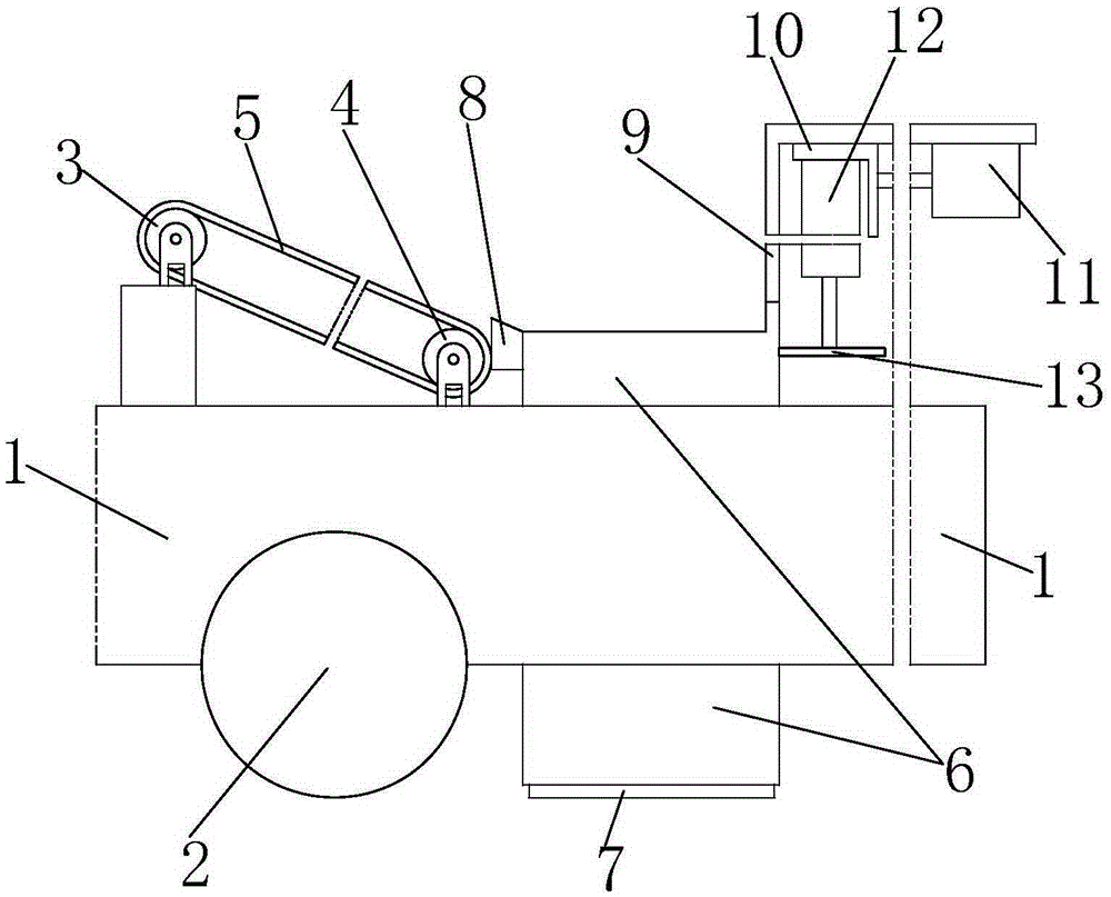
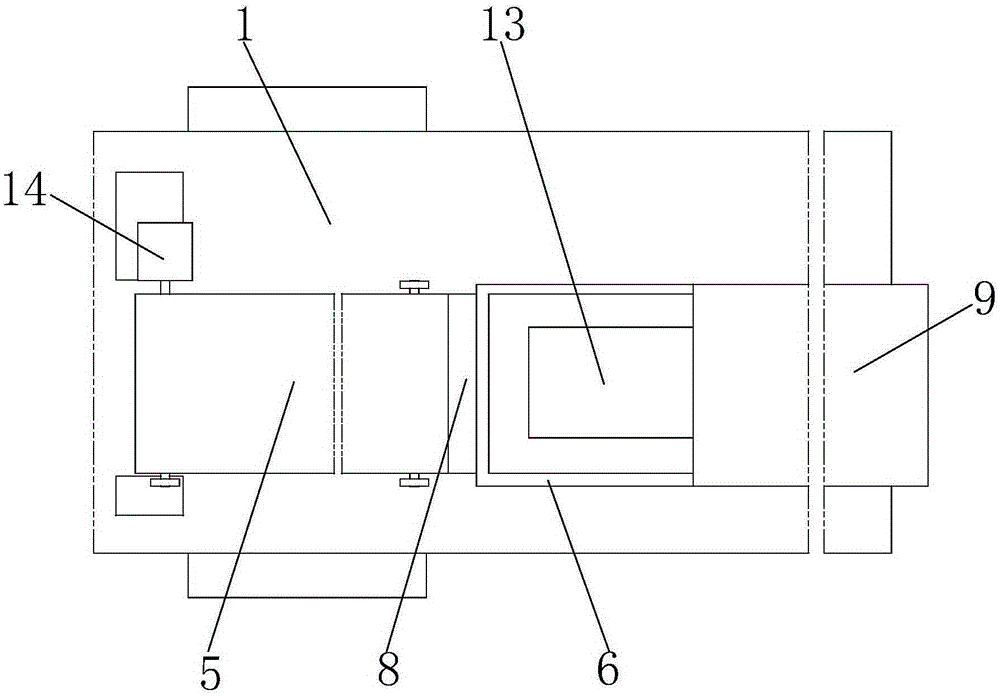
[0018] like Figure 1 to Figure 2 As shown, a positioning brick laying device for a brick laying machine mainly includes a wheel 1 and a car body 2, a No. 1 roller 3 and a No. 2 roller 4 are installed on the car body 2, and the No. 1 roller 3 and the No. 2 roller A belt 5 is connected between the 4, and a motor 14 is connected to the No. 1 roller 3.

[0019] The belt 5 is inclined to the right and down along the horizontal direction, and the right side of the belt 5 is provided with a guide plate cover 6 installed in the car body 2 in a longitudinal sliding manner, and the lower end of the iron cover 6 is fixedly connected with an iron cover 7 , the lower end of the iron sheath 6 is flush with the lower end of the wheel 1, the upper left end of the iron sheath 6 is provided with a bloc...


PUM


Abstract

The invention relates to a positioning tile laying device for a tile laying machine. The positioning tile laying device mainly comprises cart wheels, a cart body, a first rolling wheel, a second rolling wheel, a belt and a motor. The belt slants towards the lower right portion in the horizontal direction, and a guide plate sleeve is arranged on the right of the belt. The lower end of the guide plate sleeve is fixedly connected with an iron sheet sleeve, the lower end of the iron sheet sleeve is flush with the lower ends of the cart wheels, and a stopping block closely abutting against the right end of the belt is arranged at the left end of the upper portion of the iron sheet sleeve. The upper end of the stopping block is provided with a slant face with the slant angle matched with the slant angle of the belt, and the slant face at the upper end of the stopping block is higher than the upper end of the right side of the belt. An L frame plate is welded to the right end of the upper portion of the guide plate sleeve, a slipping base is horizontally installed at the lower end of the L frame plate in a sliding mode, a first air cylinder is connected to the right end of the slipping base, a second air cylinder is installed at the lower end of the slipping base, and the second air cylinder is connected with a loading plate which can be longitudinally displaced in the guide plate sleeve. By means of the positioning tile laying device, the accurate positioning effect can be achieved on the laying site of a tile; in addition, the tile can be stably conveyed to the specified laying site, placed and laid.

Description

technical field [0001] The invention relates to the field of engineering machinery, in particular to a positioning brick laying device for a brick laying machine. Background technique [0002] With the significant improvement of people's living standards in our country, house decoration is an indispensable preparation work before people live in new houses, and the first task of decoration is to lay tiles on the ground. To accelerate the speed of laying tiles, it is often considered to use corresponding tile laying machines for construction, but these tile laying machines always have difficulty in accurately locating the laying position of the tiles and placing the tiles in the designated position. SUMMARY OF THE INVENTION [0003] Aiming at the defects of the above-mentioned technologies, the present invention proposes a positioning tile laying device for a tile laying machine, which has two functions of positioning the tiles before laying and laying them smoothly. [000...

Claims


Application Information

Patent Timeline
IPC IPC(8): E04F21/22
Inventor 胡坤
Owner 广东省装饰有限公司
Learn More