
A method for realizing vertical take-off and landing of existing unmanned aircraft

An unmanned aircraft and airframe technology, applied in the aviation field, can solve the problems of flight stability, handling load loading maneuverability, weak ability to select a landing site, and length limitation of the airframe.

Active Publication Date: 2019-03-05
王泽民
View PDF6 Cites 0 Cited by
  • Summary
  • Abstract
  • Description
  • Claims
  • Application Information

AI Technical Summary

Problems solved by technology

[0004] The tail seat UAV can indeed overcome some deficiencies in the take-off and landing of the previous UAV. Because the tail seat structure supports the upright body, there is actually a problem related to stability: the difference between the longitudinal length of the body and the structural size of the tail seat. Therefore, the length of the airframe is limited, and flight stability, maneuverability, load loading, lateral air resistance, airframe size, maneuverability during vertical take-off and landing, and ability to choose a landing site are weak. insufficient

Method used


Image

  • A method for realizing vertical take-off and landing of existing unmanned aircraft
  • A method for realizing vertical take-off and landing of existing unmanned aircraft
  • A method for realizing vertical take-off and landing of existing unmanned aircraft

Examples


Embodiment 1

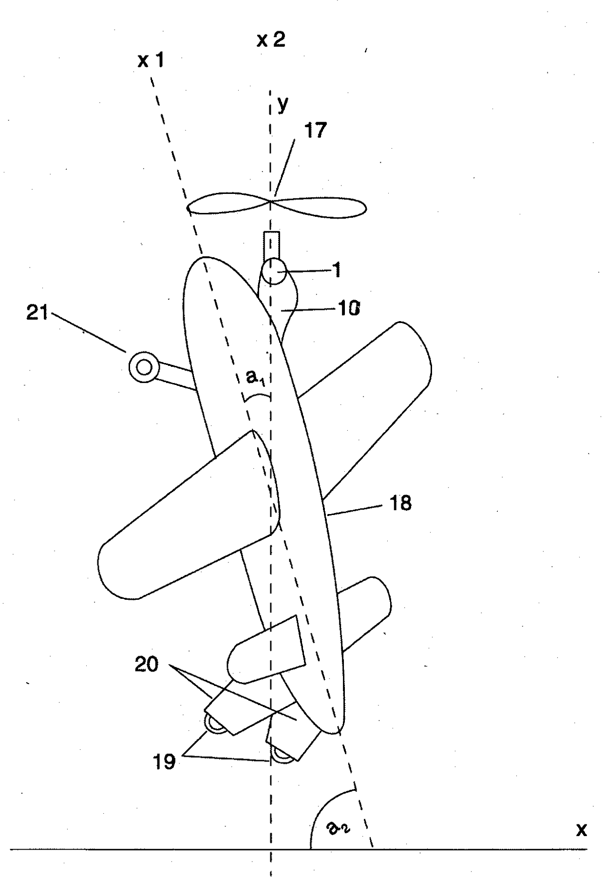
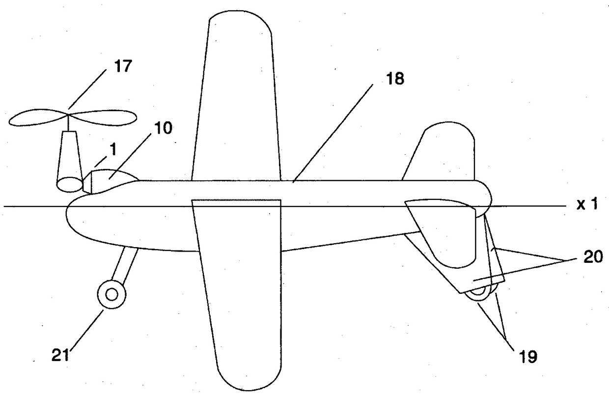
[0028] A method for realizing the vertical take-off and landing of an unmanned aircraft described in Embodiment 1, the engine 10 is installed above the horizontal centerline x1 of the body 18 .

Embodiment 1

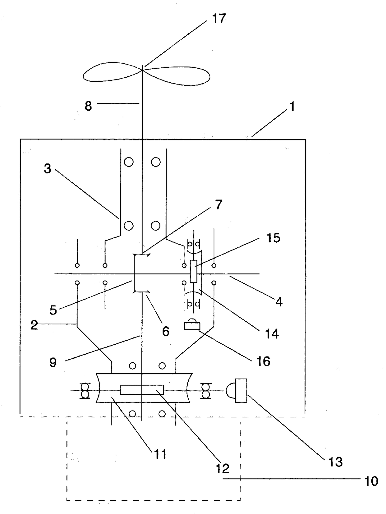
[0030] A kind of power diverter that realizes the vertical take-off and landing method of the existing unmanned aircraft described in embodiment 1 is made up of steering seat 2, steering arm 3: engine 10 power shaft 9 connects steering seat 2, and described steering seat 2 connected to the common shaft 4, the shared shaft 4 is connected to the direction arm 3, the steering seat 2 is connected to the steering worm gear 11, and the steering worm gear 11 is connected to the worm 12 and the motor 13. The worm 12 and the motor 13 are connected to the engine 10. The directional arm 3 is connected to the tilting worm gear 14 , the tilting worm gear 14 is connected to the worm 15 and the motor 16 , and the worm 15 and the motor 16 are connected to the steering seat 2 .

Embodiment 4

[0032] A method for realizing the vertical take-off and landing of the existing unmanned aircraft described in embodiment 3, the shared shaft 4 is connected to the excessive power sector gear 5, and the power transition sector gear 5 is connected to the power input sector gear while the 6 The power input sector gear 6 is connected to the engine power shaft 9, the other side of the power transition sector gear 5 is connected to the power output sector gear 7, the power output sector gear 7 is connected to the power output shaft 8, and the power output shaft 8 is connected to the direction arm 3, and the power output shaft 8 is connected to the propeller 17.

[0033] How this method works:

[0034] 1. The power converter 1 is installed on the engine power shaft 9, and consists of a steering seat 2 that can rotate around its axis, and is connected with a direction arm 3 that can tilt relative to the steering seat 2. The power of the engine 10 passes through the fan-shaped Gears ...


PUM


Abstract

A method of achieving vertical take-off and landing of an existing unmanned airplane includes a core method of installing a power turning device on an engine, an auxiliary method of changing the installation position of the engine, and an auxiliary method of employing an inverted-V-shaped lower double-inclined empennage and installing a support wheel on lower end of the empennage. By means of the method, under a horizontal status of an airframe of the existing unmanned airplane, a propeller on the nose of the airframe is tilted towards y axis, and when the included angle between the propeller and the airframe is 90 degrees, the nose of the airplane is pulled up, wherein the propeller is vertical to the y axis always to enable the airframe to be in a vertical status. The propeller pulls up the airframe to achieve the vertical take-off and landing of the unmanned airplane. During landing, when the vertical airframe slowly falls until the support wheel is landed, the pulling force of the propeller is reduced and a downward gravity is generated in the nose, and at this time, the propeller is rotated to the y axis to control the nose to slowly fall until a nose landing gear is landed to achieve landing.

Description

Technical field: [0001] The invention relates to a take-off method of an unmanned aircraft in the aviation field, in particular to an existing vertical take-off and landing method of an unmanned aircraft. Background technique: [0002] When the currently used unmanned aircraft take off, the small-sized unmanned aircraft adopts the hand-throwing take-off method, and the larger-sized unmanned aircraft uses orbit and rocket boosting to achieve take-off. Large unmanned aircraft need a runway to achieve take-off. When landing, the fences, parachutes, and runways are used to achieve landing. This method of take-off and landing brings a lot of inconvenience to the use of drones, and also limits the scope of use of unmanned aircraft. [0003] For these deficiencies in the take-off and landing of unmanned aircraft, the vd200 tail seat UAV (developed by AVIC Chengdu) is equipped with a tail seat structure at the tail of the fuselage, so that the body is in a vertical state with the no...

Claims


Application Information

Patent Timeline
Patent Type & Authority Patents(China)
IPC IPC(8): B64C29/00
Inventor 王泽民
Owner 王泽民
Learn More