
Pipe continuous cutting method

A cutting method and pipe technology, applied in the direction of tubular objects, applications, laser welding equipment, etc., can solve the problems of decreased processing efficiency of CNC laser cutting machines, and achieve the effects of saving processing time, reducing feeding times, and improving feeding efficiency

Inactive Publication Date: 2016-02-10
上海柏楚电子科技股份有限公司
View PDF5 Cites 7 Cited by
  • Summary
  • Abstract
  • Description
  • Claims
  • Application Information

AI Technical Summary

Problems solved by technology

If the size of the figure to be processed is small, the feeding action will be performed frequently; and because the feeding action and the interpolation action of the pipe axis direction during the cutting process are usually not performed on the same axis, the additional frequent reciprocating action of the feeding axis , so that the processing efficiency of the CNC laser cutting machine is significantly reduced

Method used


Image

  • Pipe continuous cutting method
  • Pipe continuous cutting method

Examples


Embodiment Construction

[0017] The present invention will be further described below according to the accompanying drawings.

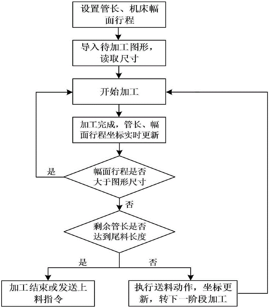
[0018] Such as figure 1 As shown, first start the processing software of the laser cutting machine, and set the length of the pipe and the stroke of the machine tool width in the software, and then import the size data of the graphics into the processing software according to the graphics to be processed.

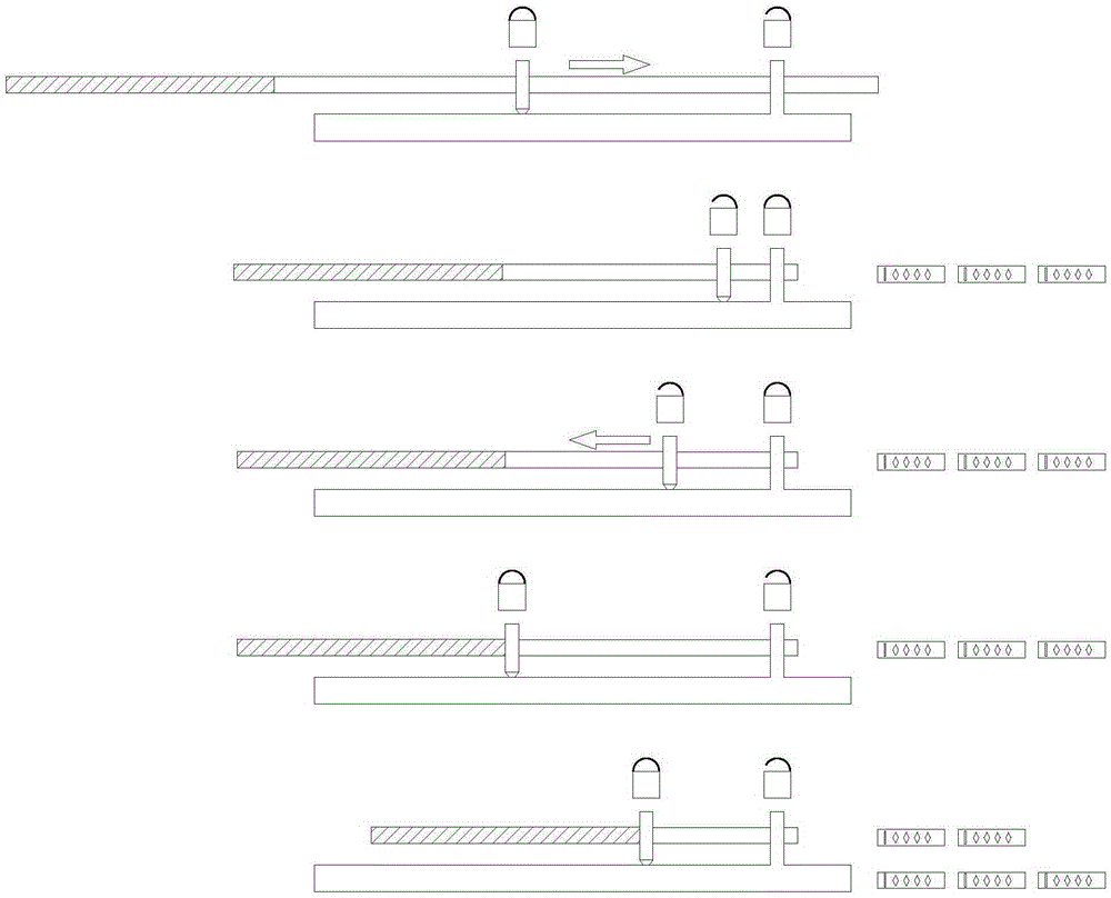
[0019] Start processing. During the processing, the cutting direction Y of the pipe axis increases, the part coordinate P increases, the feed length LengthFeeded remains unchanged, the cutting head coordinate FirstHeadDist remains unchanged, and the remaining length of the pipe to be processed decreases. At the same time, during the processing, the coordinates change in real time , but equation (1) maintains the balance:

[0020] Y+LengthFeeded=P+FirstHeadDist formula (1);

[0021] After the processing is completed, judge the relationship between the remaining stroke of ...


PUM


Abstract

The invention relates to the field of numerical control laser cutting, in particular to a pipe continuous cutting method. The pipe continuous cutting method involves a laser cutting machine and is characterized by comprising the first step that processing software of the laser cutting machine is started, and cutting parameters are set; the second step that the size of a pattern to be machined is read; the third step that laser cutting is carried out; the fourth step that feeding judgment is executed; the fifth step that when feeding judgment is executed, if the length of a remaining pipe to be machined is larger than or equal to the breadth stroke needed by one-time machining of a machine tool, a feeding request is sent, and if not, the sixth step is executed; and the sixth step that feeding movements are executed or machining is ended. Compared with the prior art, the feeding frequency in the pipe continuous cutting process can be reduced substantially, the feeding efficiency is improved, and machining time is shortened; the feeding movements are executed by an interpolation shaft for cutting movements, and multiple feeding movements are combined into one-time feeding, so that the whole pipe continuous machining process is more efficient.

Description

technical field [0001] The invention relates to the field of numerically controlled laser cutting, in particular to a continuous cutting method for pipes. Background technique [0002] In the laser cutting process, the continuous cutting of pipes has always been a basic problem. The continuous cutting of pipes is a solution for automatic feeding during the processing of pipes whose length exceeds the working stroke of the cutting machine. The traditional continuous cutting is completed by using multiple feeding actions. Each time a graphic is processed, the feeding action is called once to ensure that the pipe to be cut is within the working stroke, and then the processing of the next graphic is started. If the size of the figure to be processed is small, the feeding action will be performed frequently; and because the feeding action and the interpolation action of the pipe axis direction during the cutting process are usually not performed on the same axis, the additional ...

Claims


Application Information

Patent Timeline
Patent Type & Authority Applications(China)
IPC IPC(8): B23K26/38B23K101/06
CPCB23K26/38B23K2101/06
Inventor 周志祥
Owner 上海柏楚电子科技股份有限公司
Learn More