Intelligent identification wolfberry picking device
A wolfberry, intelligent technology, applied in the fields of picking machines, agricultural machinery and implements, applications, etc., can solve the problems of large lifting devices, blocked blades of collecting devices, and inflexible use.
- Summary
- Abstract
- Description
- Claims
- Application Information
AI Technical Summary
Problems solved by technology
Method used
Image
Examples
Embodiment 1
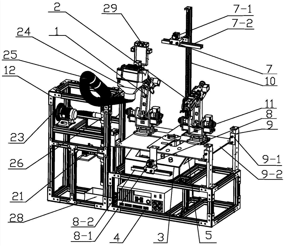
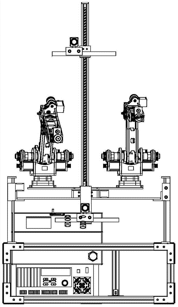
[0095] The intelligent identification wolfberry picking device includes a frame and a power supply system 5 , a control system 4 , a drive system 6 , a machine vision system, a wolfberry picking robot 1 , a branch positioning robot 2 , a wolfberry picking head and a fruit collection device arranged on the frame. The control system 4 is respectively connected with the machine vision system, wolfberry picking manipulator 1, branch positioning manipulator 2, wolfberry picking head and fruit collecting device through the drive system 6. The power supply system 5 , control system 4 and drive system 6 are all arranged in the control cabinet 3 . The power system 5 includes a lithium iron phosphate battery 5-1, an inverter 5-2 and a voltage stabilizing module 5-3; the control system 4 is an industrial computer; the control cabinet 3 also includes a touch screen 3-1 and Information Fusion Module 3-2. Among them, the lithium iron phosphate battery 5-1 is connected to the inverter 5-2 a...
Embodiment 2
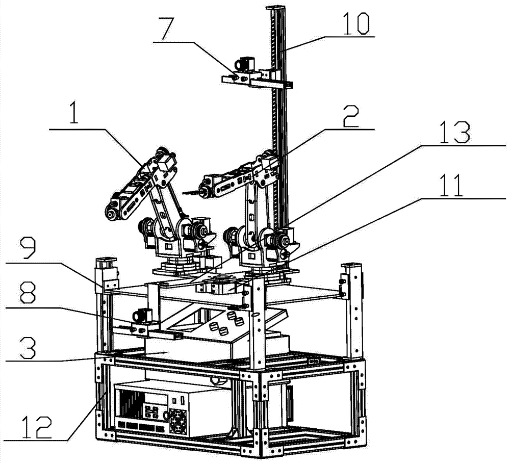
[0100] Different from Embodiment 1, the electric turntable 11 includes a turntable 11-1, a disk body 11-2, a bearing 11-3, a shaft coupling 11-4 and a servo motor 11-5. The disc body 11-2 and the servo motor 11-5 are arranged on the square table top 9-2, the rotary table 11-1 is connected with the disc body 11-2 through the bearing 11-3, and the servo motor 11-5 is connected through the The shaft coupling 11-4 is connected with the disc body 11-2.
[0101] The wolfberry picking device also includes a positioning rod 13, and the positioning rod 13 includes a front positioning rod 13-1 and a rear positioning rod 13-2. The visual lifting system 7 is fixed on the end of the rear positioning rod 13-2, and the head end of the rear positioning rod 13-2 is fixed on the edge of the turntable 11-1. The low position vision system 8 is fixed on the end of the front positioning rod 13-1, and the head end of the front positioning rod 13-1 is fixed on the edge of the turn table 11-1. The l...
Embodiment 3
[0103] The difference from Embodiment 2 is that the high-position vision system 7 includes a camera I 7-1 and a pulley two-axis smooth bar slide I7-2. The pulley double-axis light bar slide table I 7-2 includes a slide table body I 7-2a, a double-axis light bar I 7-2b, a pulley bearing I 7-2c and a slide table slider I 7-2d. The base of the camera I 7-1 is connected with the slide block I 7-2d and the pulley biaxial smooth bar slide I 7-2, and the slide body I 7-2a is connected through the L-shaped corner code I 10-4 It is connected with the slider II 10-3 of the visual lifting system 10; the two sides of the slide body I 7-2a are provided with a double-axis light bar I 7-2b, and the pulley bearing I 7-2c is fixed on the slide through an internal bearing On the slide block I 7-2d, the slide table slide block I 7-2d is installed on the slide table body I 7-2a.
[0104] The low position vision system 8 includes a camera II 8-1 and a two-axis light bar slide table II 8-2; the tw...
PUM
 Abstract
Description
Claims
Application Information
 - R&D
- Intellectual Property
- Life Sciences
- Materials
- Tech Scout
- Unparalleled Data Quality
- Higher Quality Content
- 60% Fewer Hallucinations
Browse by: Latest US Patents, China's latest patents, Technical Efficacy Thesaurus, Application Domain, Technology Topic, Popular Technical Reports.
© 2025 PatSnap. All rights reserved.Legal|Privacy policy|Modern Slavery Act Transparency Statement|Sitemap|About US| Contact US: help@patsnap.com


