
Optical waveguide and printed circuit board

An optical waveguide and pumping optical waveguide technology, applied in the field of optical communication, to avoid coupling loss, ensure normal operation, and avoid high bit error rate

Active Publication Date: 2018-09-21
罗三杰
View PDF4 Cites 0 Cited by
  • Summary
  • Abstract
  • Description
  • Claims
  • Application Information

AI Technical Summary

Problems solved by technology

[0005] Embodiments of the present invention provide an optical waveguide and a printed circuit board to solve the bottleneck problem of optical interconnection between chips

Method used


Image

  • Optical waveguide and printed circuit board
  • Optical waveguide and printed circuit board
  • Optical waveguide and printed circuit board

Examples


Embodiment Construction

[0030] The following will clearly and completely describe the technical solutions in the embodiments of the present invention in conjunction with the accompanying drawings in the embodiments of the present invention. Obviously, the described embodiments are only some of the embodiments of the present invention, not all of them. Based on the embodiments of the present invention, all other embodiments obtained by persons of ordinary skill in the art without making creative efforts belong to the protection scope of the present invention.

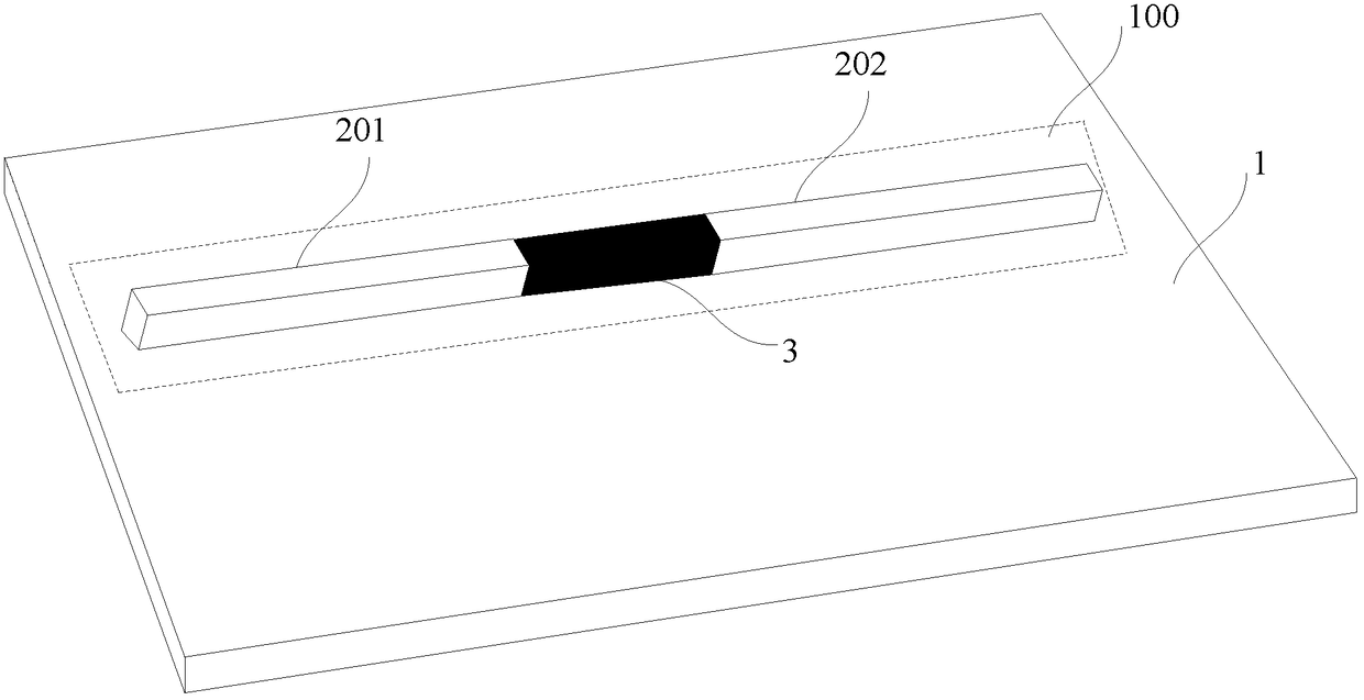
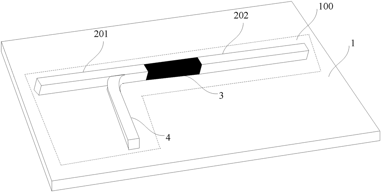
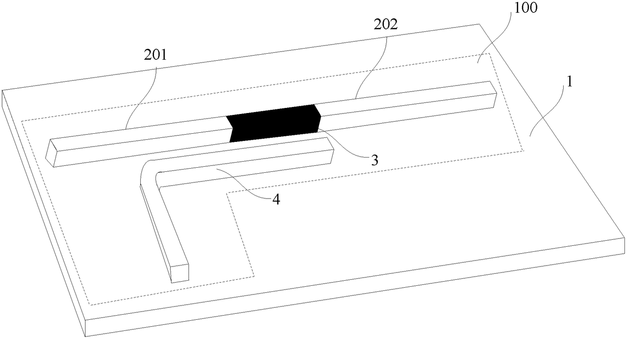
[0031] An embodiment of the present invention provides an optical waveguide, in which a gain optical waveguide connected with the signal optical waveguide is provided, and the optical signal transmitted by the signal optical waveguide is amplified through the gain optical waveguide to solve the current OE- The transmission loss of the optical signal transmitted in the PCB optical link.

[0032] An optical waveguide generally includes a waveguid...


PUM


Abstract

An optical waveguide and a printed circuit board. The optical waveguide comprises a lower clad layer (1), an upper clad layer, and a waveguide core layer formed between the lower clad layer (1) and the upper clad layer. The waveguide core layer comprises at least one waveguide unit (100). Each waveguide unit (100) comprises a signal optical waveguide used for transmitting an optical signal, and a gain optical waveguide (3) used for amplifying, under a pump effect of pump light, the optical signal transmitted by the signal optical waveguide. The signal optical waveguide and the gain optical waveguide (3) are disposed on the surface of the side of the lower clad layer (1) facing the upper clad layer, and the signal optical waveguide and the gain optical waveguide (3) are connected into an integral structure by means of end surfaces, so that normal operation of the system can be ensured, and the optical interconnection bottleneck problem caused by great loss of optical signal transmission can be avoided.

Description

technical field [0001] The invention relates to the field of optical communication, in particular to an optical waveguide and a printed circuit board. Background technique [0002] With the continuous improvement of the demand for high-speed data transmission, data centers need multiple processors to cooperate to complete the processing of related data, which makes the data center's requirements for the interconnection bandwidth between chips become higher and higher. Therefore, printing in the system The interconnection rate, bandwidth and channel density between printed circuit boards (Printed circuit board, PCB) and / or between chips on the PCB all put forward higher requirements. [0003] The traditional electrical interconnection method based on metal wires between chips on the PCB has serious transmission loss and limited transmission distance during high-speed data transmission due to the inherent physical characteristics of the metal wire itself (the higher the transm...

Claims


Application Information

Patent Timeline
Patent Type & Authority Patents(China)
IPC IPC(8): G02B6/02
CPCG02B6/02
Inventor 王攀
Owner 罗三杰
Learn More