
Semiconductor structure manufacturing method

一种制作方法、半导体的技术,应用在半导体/固态器件制造、半导体器件、电气元件等方向,能够解决无法解决技术缺失等问题

Active Publication Date: 2016-02-03
UNITED MICROELECTRONICS CORP
View PDF9 Cites 0 Cited by
  • Summary
  • Abstract
  • Description
  • Claims
  • Application Information

AI Technical Summary

Problems solved by technology

[0004] However, as the scale of semiconductor devices continues to shrink, even using non-planar field effect transistor devices and strained silicon technology at the same time cannot solve all technical deficiencies

Method used


Image

  • Semiconductor structure manufacturing method
  • Semiconductor structure manufacturing method
  • Semiconductor structure manufacturing method

Examples


Embodiment Construction

[0025] In order to enable those who are familiar with the technical field of the present invention to further understand the present invention, the preferred embodiments of the present invention are specifically listed below, and with the accompanying drawings, the composition of the present invention and the desired effects are described in detail. .

[0026] For the convenience of description, the drawings of the present invention are only schematic diagrams for easier understanding of the present invention, and the detailed proportions thereof can be adjusted according to design requirements. Those skilled in the art should be able to understand the upper and lower relationships of relative elements in the figures described in the text to refer to the relative positions of objects, so they can be turned over to present the same components, which should all belong to the disclosure of this specification The range is described here.

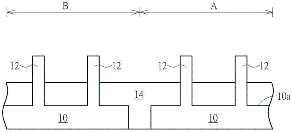
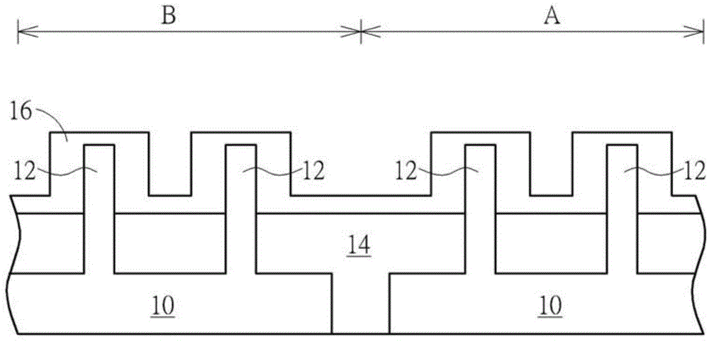
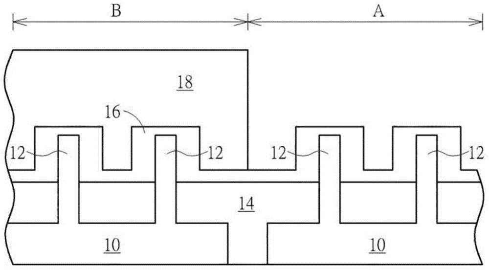
[0027] Figure 1 to Figure 9 A schematic...


PUM


Abstract

The invention discloses a semiconductor structure manufacturing method which at least comprises the following steps: to begin with, providing a substrate, wherein a first area of the substrate comprises a plurality of fin-shaped structures and an insulation layer arranged on the substrate and between the fin-shaped structures; then, forming a first material layer covering the fin-shaped structures and the insulation layer; and partially removing the fin-shaped structures and forming at least one epitaxial layer on the top portion of each residual fin-shaped structure.

Description

technical field [0001] The invention relates to the field of semiconductor manufacturing technology, in particular to a manufacturing process for avoiding the mutual contact between an epitaxial layer formed on a fin structure and other adjacent epitaxial layers. Background technique [0002] As the size of field effect transistors (FETs) continues to shrink, the development of existing planar field effect transistors is facing the limit of the manufacturing process. In order to overcome the limitations of the manufacturing process, it has become increasingly popular to replace planar transistor elements with non-planar field effect transistor elements, such as multi-gate field effect transistor (multi-gate MOSFET) elements and fin field effect transistor (finfield effect transistor, FinFET) elements. The current mainstream development trend. Since the three-dimensional structure of the non-planar transistor element can increase the contact area between the gate and the fin...

Claims


Application Information

Patent Timeline
Patent Type & Authority Applications(China)
IPC IPC(8): H01L21/336
CPCH01L29/165H01L29/66795H01L21/823431H01L21/823418H01L29/7848H01L29/66636
Inventor 简金城
Owner UNITED MICROELECTRONICS CORP
Learn More