Eureka AIR delivers breakthrough ideas for toughest innovation challenges, trusted by R&D personnel around the world.

Method for Lifetime Evaluation of Electrolytic Capacitors in Motor Drive Bus

A technology of motor drivers and electrolytic capacitors, which is applied in the direction of instruments, measuring electronics, scientific instruments, etc., can solve the problems that cannot be used as engineering verification means, the accuracy of calculation results is poor, and the calculation results have large differences, so as to achieve accurate and effective evaluation results and calculation errors. Small, consider the overall effect

Active Publication Date: 2018-05-04
NANJING ESTUN AUTOMATION CO LTD
View PDF5 Cites 2 Cited by
  • Summary
  • Abstract
  • Description
  • Claims
  • Application Information

AI Technical Summary

Problems solved by technology

[0005] At present, the method for evaluating the life of the electrolytic capacitor on the drive bus, one is the ripple current test method, which calculates the life of the capacitor by testing the ambient temperature, ripple current, and actual applied voltage of the electrolytic capacitor, but the calculation process is more complicated. Poor accuracy, only suitable for initial design selection, not as a means of engineering verification
The other is the thermal resistance calculation method, which calculates the life of the capacitor through the ESR of the electrolytic capacitor and the ripple current at different frequencies. The acquisition of the key parameter ESR requires a large amount of data accumulation support, otherwise the calculation result is quite different from the actual one. The method is only suitable for the initial selection design

Method used


Image

  • Method for Lifetime Evaluation of Electrolytic Capacitors in Motor Drive Bus
  • Method for Lifetime Evaluation of Electrolytic Capacitors in Motor Drive Bus
  • Method for Lifetime Evaluation of Electrolytic Capacitors in Motor Drive Bus

Examples


Embodiment Construction

[0026] In order to specifically illustrate the technical solutions, technical effects and features of the present invention, the following will describe the present invention more clearly and in detail with specific examples in conjunction with the accompanying drawings of the embodiments of the present invention.

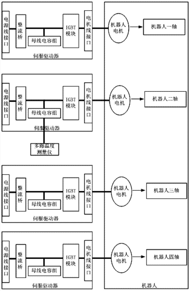
[0027] Embodiment: The test object is a servo driver in a 180Kg 4-axis robot system.

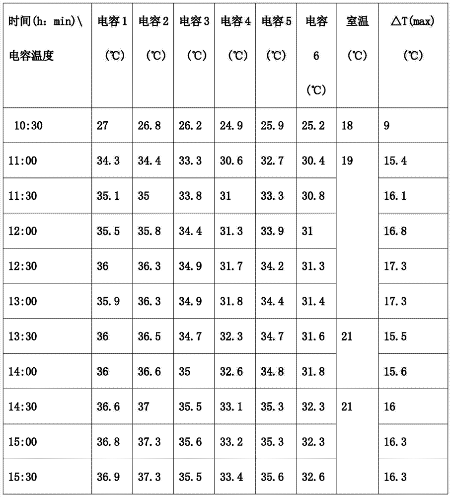
[0028] When the robot body simulates the actual working conditions, the 2-axis 7.5Kw servo driver drives the motor to perform fast forward and reverse motion at a speed of 3500rpm. Compared with other axes, the load inertia of the 2-axis is the largest, and the frequency of the forward and reverse rotation of the motor is the highest. The stroke is the longest, so the DC bus voltage fluctuation of the 2-axis servo driver is the largest, the ripple current of the bus electrolytic capacitor is the largest, and the life of the 2-axis servo driver is the shortest. Therefore, this spe...


PUM


Abstract

The present invention is a method for evaluating the life of electrolytic capacitors on the busbars of motor drivers. The heat-sensitive technology is used to test the core temperature and the working environment temperature of each busbar electrolytic capacitor of the driver, and the highest core temperature rise ΔT among all the electrolytic capacitors is selected to calculate the driver. When working under the condition of the upper limit temperature of the environment, the temperature of the core of the electrolytic capacitor is T2. According to the difference between the maximum allowable core temperature and T2, and the correction factor of the bus voltage, calculate the life of the electrolytic capacitor of the bus to achieve the purpose of evaluating the life of the driver. The method of the present invention considers the influence brought by the actual upper limit of the operating temperature of the driver and the temperature difference of the test environment, the influence brought by the bus voltage level during actual use, and the influence brought by the uneven temperature rise between the electrolytic capacitors of the bus. Considering comprehensively, The evaluation results are reliable.

Description

technical field [0001] The invention relates to a method for testing and evaluating the life of an electrolytic capacitor of a motor driver bus, which is used for evaluating the life of the driver. Background technique [0002] With the advancement of automation technology and the continuous development of industrial automation, servo and frequency conversion systems are widely used in manufacturing, medical treatment, entertainment, service and other industries. The purpose is to provide accurate and fast position control, which is indispensable in the field of advanced manufacturing technology. Advanced automation equipment, its technical level and application degree are an important symbol of a country's industrial automation. [0003] With the promotion and application of servo and frequency conversion systems, the demand for their performance is getting higher and higher, including shorter positioning time, better control stability, smarter self-tuning technology, and h...

Claims


Application Information

Patent Timeline
Patent Type & Authority Patents(China)
IPC IPC(8): G01R31/00G01K7/22
Inventor 姚瑱刘虎徐小军戴安刚吴波
Owner NANJING ESTUN AUTOMATION CO LTD
Why Eureka
Eureka Blog
Learn More