Al technical title is built by PatSnap Al team. It summarizes the technical point description of the patent document.
A sweeping vehicle and main sweeping brush technology, which is applied in the field of sanitation and cleaning, can solve the problems of the limited cleaning range of the sweeping vehicle, cannot meet the needs of the sweeping vehicle, and occupy a large volume of the frame, and achieve a compact structure, convenient control, and high reliability. Effect
Active Publication Date: 2017-01-04
QINGDAO ALLITE AUTO TECHNIC
View PDF8 Cites 0 Cited by
Summary
Abstract
Description
Claims
Application Information
AI Technical Summary
This helps you quickly interpret patents by identifying the three key elements:
Problems solved by technology
Method used
Benefits of technology
Problems solved by technology
The cleaning vehicle in the prior art has the following problems in practical application: (1) the cleaning vehicle in the prior art, its parts such as engine, machine oil tank, diesel oil tank, material storage box etc. are placed scatteredly on the frame, Occupies a larger frame size; (2) The current sweeper is driven in a front-wheel drive mode. This type of drive mode directly drives the front wheels with a half shaft after the engine power passes through the differential, without the need for a transmission shaft. The power loss is small; however, since the front wheels are responsible for driving and steering at the same time, the steering radius is relatively large, and the problem of understeer is prone to occur; (3) the current sweeper only has two main sweeping brush arms, two main sweeping brushes The brush arms are all connected to the car frame; although the two main sweeping arms can clean the garbage within a certain range in front of the sweeper, left front or right front; however, due to the limited cleaning range of the sweeper, it cannot Clean up the rubbish on the curb; (4) The spray device currently used cannot meet the needs of the updated sweeper because it only has two dust-reducing pipelines connected to the main sweeping brush.
Method used
Image
Click on the blue label to locate the original text in one second.
Reading with bidirectional positioning of images and text.
Examples
Embodiment Construction
[0031] Below in conjunction with accompanying drawing and specific embodiment the present invention is described in further detail:
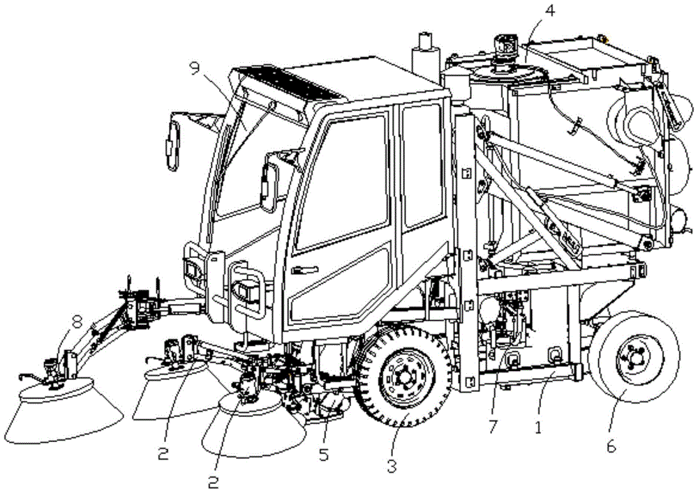
[0032] combine figure 1 As shown, the cleaning vehicle includes frame 1, cab 9, main sweeping brush device 2, front wheel assembly 3, material storage box 4, garbage collection device 5, oil tank, engine, diesel tank, rear wheel assembly 6 and spraying device 7.
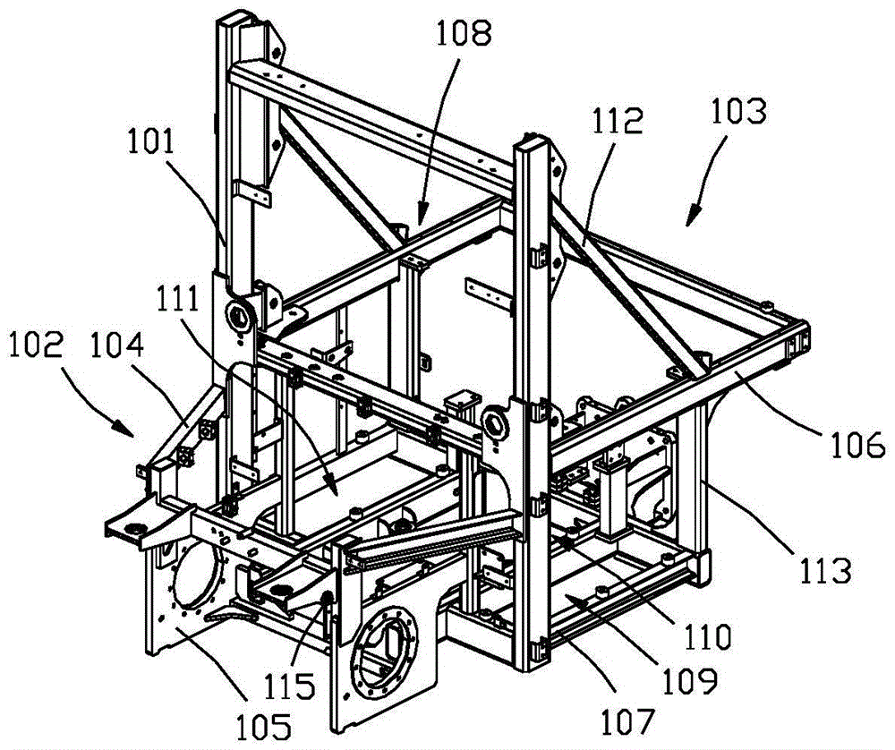
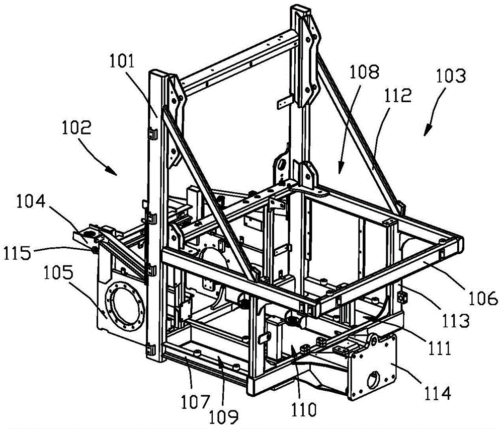
[0033] like figure 2 and image 3 As shown, the frame 1 includes a longitudinal support 101; with the longitudinal support 101 as a boundary, the frame is divided into two installation areas, front and rear, which are respectively a front installation area 102 and a rear installation area 103.
[0034] In the front mounting area 102, a cab mounting frame 104, a main sweeping device mounting frame 115 and a front wheel assembly mounting frame 105 are sequentially arranged from top to bottom. Wherein, the cab mounting frame 104 is used for mounting the cab 9 , the main sweeping devi...
PUM
Abstract
The invention discloses a motor sweeper. The motor sweeper comprises a machine frame, a cab, a main sweeping device, an auxiliary sweeping device, a front wheel assembly, a storage box, a garbage collecting device, a sump, an engine, a diesel tank, a rear wheel assembly, a sprinkling device and the like. By reasonably designing the machine frame, the main sweeping device, the auxiliary sweeping device, the front wheel assembly, the storage box, the rear wheel assembly, the sprinkling device and other components, the frame structure of the motor sweeper is more compact, the mechanical control part of the main sweeping device is designed more reasonably, the sweeping range of the motor sweeper is widened, front wheel control is more accurate, the structure of the storage box is better optimized, the steering radius of rear wheels is reduced, and the sprinkling device is designed to be better adapted to the improved motor sweeper structure. On the basis that the functions of the motor sweeper are enriched, the working efficiency of the motor sweeper is improved remarkably.
Description
technical field [0001] The invention belongs to the technical field of sanitation and cleaning, and in particular relates to a sweeping vehicle. Background technique [0002] The cleaning vehicle in the prior art includes a frame, a cab, a main sweeping device, a front wheel assembly, a material storage box, a garbage collection device, an oil tank, an engine, a diesel tank, a rear wheel assembly and a spraying device The cab, the main sweeping device and the front wheel assembly are installed at the front of the frame, and the storage box, engine, diesel tank and oil tank are installed at the rear of the frame. The cleaning vehicle in the prior art has the following problems in practical application: (1) the cleaning vehicle in the prior art, its parts such as engine, machine oil tank, diesel oil tank, material storage box etc. are placed scatteredly on the frame, Occupies a larger frame size; (2) The current sweeping vehicle is driven in a front-wheel drive mode. This typ...
Claims
Application Information
Patent Timeline
Application Date:The date an application was filed.
Publication Date:The date a patent or application was officially published.
First Publication Date:The earliest publication date of a patent with the same application number.
Issue Date:Publication date of the patent grant document.
PCT Entry Date:The Entry date of PCT National Phase.
Estimated Expiry Date:The statutory expiry date of a patent right according to the Patent Law, and it is the longest term of protection that the patent right can achieve without the termination of the patent right due to other reasons(Term extension factor has been taken into account ).
Invalid Date:Actual expiry date is based on effective date or publication date of legal transaction data of invalid patent.