


Quick Research
Generate reliable direction feasibility study reports for your R&D in just a few steps.

Technical Q&A
Discover and master advanced knowledge NOW. Basics, ideas, possibilities, all at once.

Find Solutions
As an expert in R&D theories, this can generate solutions to your technical problems instantly.

Evaluate Feasibility
Analyze your overall solution with one click, know your potential R&D risks in advance.

Monitor Landscape
Get weekly tech updates, stay abreast of the latest tech innovations and key insights.
Electronic pen, printing equipment and printing method
A technology for electronic pens and printing equipment, applied in printing, typewriters, etc., can solve the problems of difficulty in recovery, the influence of external disturbances on shape and charge distribution, poor stability of Taylor cones, etc., and achieve the effect of resisting external disturbances
- Summary
- Abstract
- Description
- Claims
- Application Information
AI Technical Summary
Problems solved by technology
Method used
Image

Examples
Embodiment 1
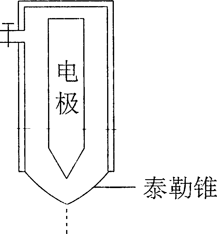
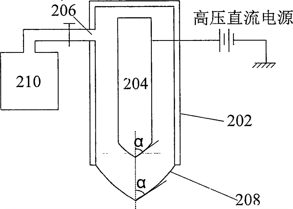
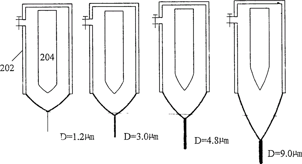
[0040] figure 2 is a schematic diagram showing an electronic pen (also called a maskless controllable electronic pen because it can be used to directly form a wiring pattern on a substrate by printing) according to an embodiment of the present invention. Such as figure 2 As shown, the electronic pen 200 of this embodiment includes: a housing 202 and an electrode 204, the housing 202 has an input port 206 at the upper part and a discharge hole 208 at the bottom, and the electrode 204 is located at the center of the housing 202 . The discharge hole 208 is preferably circular and the electrode 204 is aligned with the center of the discharge hole 208 . The electrode 204 has a free end (which is a tapered end) adjacent to the discharge hole 208, and the tapered end of the electrode 204 is designed according to the shape of the liquid Taylor cone desired to be formed at the discharge hole 208, i.e., the electrode 204 The tapered end is formed to match the desired liquid Taylor ...
no. 2 Embodiment
[0045] Combine below Figure 4 The second embodiment of the present invention will be described.
[0046] In order to further obtain a liquid thin beam with a required diameter and a more stable thin-beam jet, the structure of the electrode is further improved in this embodiment. Specifically, a plurality of protrusions (a plurality of sharp metal burrs formed on the tapered end of the electrode during the fabrication of the electrode) are formed on the tapered end of the electrode. Figure 4 A schematic structural view showing a plurality of protrusions 212 formed on the tapered end of the electrode according to the second embodiment of the present invention. Such as Figure 4 As shown, these protrusions 212 are arranged on the tapered end surface of the electrode according to the surface curvature of the tapered end surface, that is, the arrangement density of these protrusions 212 is proportional to the curvature of the tapered end surface everywhere. The greater the cur...
no. 3 Embodiment
[0050] The following will combine Figure 5 A third embodiment of the present invention will be described.
[0051] This third embodiment provides an electronic pen with an improved electrode structure. The electronic pen in this embodiment uses the principle of electrostatic spraying to form a liquid Taylor cone at the discharge hole, thereby forming a thin liquid beam, and the charge injected into the liquid through the electrode is mainly distributed in the Taylor cone and its vicinity, so that small external disturbances can be eliminated. It is possible to cause the redistribution of charges in the Taylor cone and its vicinity, which will generate a small current in the local Taylor cone, which will affect the shape of the Taylor cone, and the change of the shape of the Taylor cone will inevitably cause the change of the diameter of the thin liquid beam . In view of this, in this embodiment, the electrode structure is improved, so that the shape of the Taylor cone is no...
PUM
 Abstract
Description
Claims
Application Information
 - R&D Engineer
- R&D Manager
- IP Professional
- Industry Leading Data Capabilities
- Powerful AI technology
- Patent DNA Extraction
Browse by: Latest US Patents, China's latest patents, Technical Efficacy Thesaurus, Application Domain, Technology Topic, Popular Technical Reports.
© 2024 PatSnap. All rights reserved.Legal|Privacy policy|Modern Slavery Act Transparency Statement|Sitemap|About US| Contact US: help@patsnap.com