Hydraulic feeding device

A hydraulic and feeding claw technology, applied in the field of metallurgical forging, can solve problems such as fine and complex structures, damage, and decreased control accuracy

Inactive Publication Date: 2016-02-03
WUXI QINGYANG MACHINERY MFG
View PDF5 Cites 2 Cited by
  • Summary
  • Abstract
  • Description
  • Claims
  • Application Information

AI Technical Summary

Problems solved by technology

In a hydraulic system containing an electro-hydraulic servo mechanism, the structure of the valve is fine and complex, and the sharp edge of the spool of the control valve is easily damaged by the solid particles contained in the hydraulic oil, resulting in a decrease in control accuracy, and in severe cases System control failure

Method used


Image

  • Hydraulic feeding device

Examples


Embodiment 1

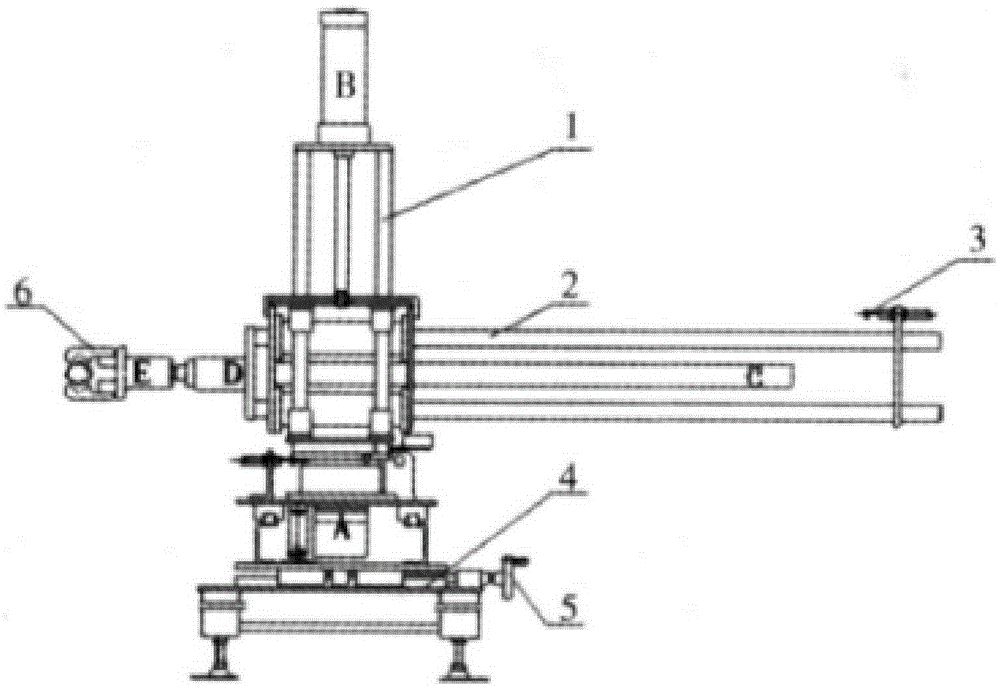
[0021] The device is fixed to the ground through four cylindrical legs. After the base is fixed on the ground, the rotating hydraulic table is fixed to the base. The rotating hydraulic table controls its rotation angle through hydraulic pressure. The rotation range is 0°-240°, and the liquid inlet is controlled Entry and exit of hydraulic media. Then install the screw device on the rotating hydraulic platform, and fix it by bolts. There are three screw columns, as shown in the figure, and then install the corresponding hydraulic cylinder on the square positioning box. The threaded hole matched with the rod column sets the positioning box on the lead screw. The height adjustment range of the positioning box is 200mm-800mm. The feeding claw is connected to the top of the hydraulic cylinder, so that the feeding claw can adjust its running length along with the expansion and contraction of the hydraulic cylinder, and its length adjustment range is 160mm-960mm. After the installat...


PUM


Abstract

The invention discloses a hydraulic feeding device. The hydraulic feeding device is fixed to the ground through four cylindrical legs. After a base is fixed to the ground, a rotating hydraulic table is fixed to the base, the rotating angle of the rotating hydraulic table is controlled hydraulically, the rotating range is 0-24 degrees, and a liquid inlet controls entering and exiting of liquid media. Then, a screw device is installed on the rotating hydraulic table and is connected and fixed through a bolt, and three screw pillars are arranged and are shown in the drawing. Afterwards, a corresponding hydraulic cylinder is installed on a square positioning box, the square positioning box is provided with three threaded holes matched with the screw pillars, the positioning box is arranged on a screw in a sleeving manner, and the height adjusting range of the positioning box is 200-800 mm. A feeding jaw is connected with the top of the hydraulic cylinder, and therefore the running length of the feeding jaw can be adjusted along with stretching and contracting of the hydraulic cylinder, wherein the length adjusting range of the feeding jaw is 160 mm-960 mm.

Description

technical field [0001] The invention relates to the field of metallurgical forging, in particular to a hydraulic feeding device. Background technique [0002] Hydraulic transmission is a form of transmission in which fluid is used as the working medium to transmit and control energy. Compared with electric drive and mechanical transmission, hydraulic transmission has the advantages of large output force, compact structure, small volume, convenient speed regulation and easy control, so it is widely used in construction machinery, construction machinery and machine tools and other equipment. [0003] Modern hydraulic transmission technology was promoted by the rising and flourishing oil industry in the 19th century. The earliest successful hydraulic transmission device was the turret indexer on the ship. Later, hydraulic hexagonal lathes and grinding machines appeared, and some general-purpose lathes came to Hydraulic transmission was not used until the late 1930s. During Wo...

Claims


Application Information

Patent Timeline
Patent Type & Authority Applications(China)
IPC IPC(8): B21K27/00
CPCB21K27/00
Inventor 唐靖岚
Owner WUXI QINGYANG MACHINERY MFG
Why Eureka
Try Eureka