Threshing device of harvester

A technology of threshing device and harvester, which is applied to harvesters, threshing equipment, cutters, etc., can solve the problems of increasing equipment cost, less time, and no consideration, and achieve the effects of improving threshing efficiency, increasing contact rate, and reducing resistance.

Active Publication Date: 2016-02-03
刘念湘
View PDF9 Cites 1 Cited by
  • Summary
  • Abstract
  • Description
  • Claims
  • Application Information

AI Technical Summary

Problems solved by technology

[0002] In the prior art, most of the threshing devices of the harvester are threshing drums rotating and threshing. The threshing process does not consider the cooperation with the grass guiding device and the grass pressing parts. The movement trajectory of the pressing part on the device intersects with the threshing cylinder in a tangent line, and there is only one closest tangent point. In this way, when the grain is introduced into the pressing process, the upper part of the straw only touches the threshing cylinder once and is hit by the threshing teeth on the threshing cylinder. The threshing effect is not good; and the threshing teeth or threshing nails on the existing threshing cylinder are mostly arranged in a one-way oblique manner, which requires a special cleaning device to clean and remove impurities, which increases the cost of the equipment; as announced No. CN203467221U's "a self-propelled threshing miniature harvester before cutting", and the patent No. 200910044696.7's "less feeding, first off and then mowing type rice harvesting method and its miniature combine harvester", all have short effective escape paths. , less time and above defects

Method used


Image

  • Threshing device of harvester
  • Threshing device of harvester
  • Threshing device of harvester

Examples


Embodiment 1

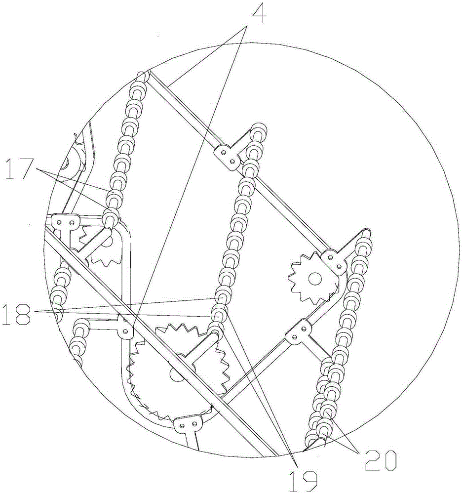
[0022] refer to figure 1 , figure 2 , the present embodiment includes a threshing cylinder 1, the surface of the threshing cylinder 1 is provided with a plurality of threshing teeth 2, and also includes a grain guide 3, and the grain guide 3 includes a grain guide chain 4, a plurality of grain guide sprockets, and a plurality of root presses. Grain cross bar 6 and grain pressing cross bar 6 are fixed overhead on the grain guiding chain 4 and move back and forth with the grain guiding chain 4. The grain guiding chain 4 is located above or on the side of the threshing drum 1, and it is in the same position as the section near the threshing drum 1. Approximate " W " shape, i.e. double " V " shape, there are two nearest tangent points between the pressing grain horizontal bar 6 and the threshing cylinder 1 that are contained on it. There are two grass-guiding chains 4, two groups of grass-guiding sprockets, two groups of grass-guiding sprockets and two grass-guiding chains move ...


PUM


Abstract

The invention discloses a threshing device of a harvester and belongs to the field of harvesting equipment components. The threshing device comprises a threshing cylinder, multiple threshing teeth are arranged on the surface of the threshing cylinder, the threshing device further comprises a crop guiding device, the crop guiding device comprises crop guiding chains, crop guiding chain wheels and multiple crop pressing cross bars, the crop pressing cross bars are fixed to the crop guiding chains and circularly move along with the crop guiding chains, the crop guiding chains are located over or above the threshing cylinder, multiple continuous V shapes are formed by the crop guiding chains and threshing cylinder approaching sections, and when moving to the bottom ends of the multiple V shapes along with the crop guiding chains, multiple nearest tangent points are formed between the crop pressing cross bars and the threshing cylinder. By means of the threshing device of the harvester, the crop bars can be twisted continuously and dynamically, the striking direction is changed, the crop ear tip positions are struck multiple times, no special cleaning device is needed to be installed, and the threshing cylinder can achieve the automatic foreign-matter discharging function and the cleaning function.

Description

technical field [0001] The invention relates to a part of a harvester, in particular to a threshing device of the harvester. Background technique [0002] In the prior art, the threshing device of the harvester is mostly a threshing drum rotating threshing, and the threshing process does not consider the cooperation with the grass guiding device and the grass pressing parts. The movement trajectory of the pressing parts on the device intersects the threshing cylinder tangentially, and there is only one closest tangent point. In this way, when the grain is introduced into the pressing process, the upper part of the straw only touches the threshing cylinder once and is hit by the threshing teeth on the threshing cylinder. The threshing effect is not good; and the threshing teeth or threshing nails on the existing threshing cylinder are mostly arranged in a one-way oblique manner, which requires a special cleaning device to clean and remove impurities, which increases the cost ...

Claims


Application Information

Patent Timeline
IPC IPC(8): A01F12/22A01D41/12
Inventor 刘念湘
Owner 刘念湘
Why Eureka
Try Eureka