High-magnitude axial compression and binding joint load realization device

A combined load, high-level technology, used in the testing of measuring devices, instruments, and mechanical components, can solve the problem of easy interference between the loading device and the frame structure, and achieve the effect of overcoming self-weight.

Active Publication Date: 2016-01-27
BEIJING INST OF STRUCTURE & ENVIRONMENT ENG +1
View PDF7 Cites 8 Cited by
  • Summary
  • Abstract
  • Description
  • Claims
  • Application Information

AI Technical Summary

Problems solved by technology

[0007] During the design process of the test scheme, it is first necessary to solve the problem caused by the axial compression load T applied to the two engine installations on the engine frame is close to 123 tons. There are two main difficulties. First, the two engine installations at the upper end of the frame Only the four Φ13 connecting holes arranged in a square with a pitch of 183 can be used. The centers of the four holes are solid, and the conventional method cannot be used to directly pull down the connecting rod in the middle to realize the load, and the frame is a multi-bar structure. With multiple staggered rod systems, the loading device and the frame structure itself are likely to interfere; secondly, there is no high load-bearing point on the platform corresponding to the axial compression load, which can only be realized through the T-shaped slot on the platform, and a nail on the T-shaped slot The location of the platform can only bear a load of 10t / 100mm, and the area of ​​the loading point of the concentrated load is Φ72mm. How to increase the force-bearing area of ​​the platform so that it can withstand a load of 123t has become another problem

Method used


Image

  • High-magnitude axial compression and binding joint load realization device
  • High-magnitude axial compression and binding joint load realization device
  • High-magnitude axial compression and binding joint load realization device

Examples


Embodiment Construction

[0028] The present invention will be described in detail below in conjunction with the accompanying drawings and specific embodiments.

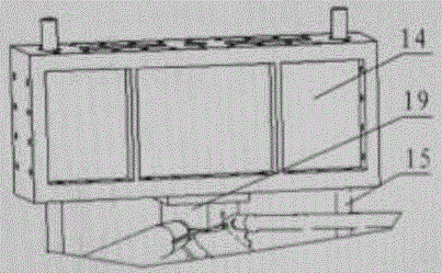
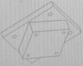
[0029] Such as image 3 — Figure 5 As shown, the high-level axial compression and binding combined load realization device of the present invention includes four 12m high-strength beams 1, 18 supporting column blocks 2, 8 corner braces 3, eight 1m column blocks 4, two 7m high-strength beams 5, 14 load application devices 6, two high-strength column beams 7, 1 load-bearing steel frame 8, 1 test platform 9, 8 fixed beams 10, 2 bearing walls 11, 2 sides Top column block 12, 4 loading angle braces 13, 4 loading beams 14, 4 tie rods 15, 2 fixing square plates 16, 1 fixing ring 17 and transition tooling 19; The force gauge and the connecting rod are connected by threads;

[0030] Axial compression load realization device connection relationship: the combined test piece 18 includes, from top to bottom, the first-level engine frame, the first-lev...


PUM


Abstract

The invention belongs to the technical field of structure static test, and specifically relates to a high-magnitude axial compression and binding joint load realization device. A combined test piece, a bearing steel box and a test platform are sequentially connected by bolts from top to bottom, and the test platform is fixed on the ground. A loading transition tool is connected to an engine installation site above a frame. Loading beams are connected above the loading transition tool. Two pull rods are respectively connected to the long holes at the two ends of each loading beam. Each pull rod is connected with a loading frame after passing through a first-stage engine frame. Load applying devices are connected below the loading beams. The load applying devices are sequentially connected downward with fixed square plates and a fixed ring by bolts. First, the fixed ring and the test platform are connected by a T slot; second, the fixed square plates, the fixed ring and the T slot of the test platform are connected by multiple bolts in a three-to-one mode; and finally, through holes are arranged in the corresponding positions of the square plates above the already-made bearing point of the fixed ring to connect the fixed ring and the fixed square plate.

Description

technical field [0001] The invention belongs to the technical field of structural static tests, and in particular relates to a high-level axial compression and binding combined load realization device. Background technique [0002] The first-stage post-transition section is an important section in the development process of a new model, with a diameter of 5000mm and a height of 950mm. It is a component of the first-stage hydrogen tank and is located between the first-stage hydrogen tank and the first-stage tail section. Its front end is connected with the rear short shell of the first-stage hydrogen tank, and its rear end is connected with the first-stage tail section and the first-stage engine. Due to the change in the binding form, the stress form of the rear transition section of this model is different from that of the existing domestic binding models. The rear transition section of the existing model only bears the thrust of the engine, while the new model has a rear tr...

Claims


Application Information

Patent Timeline
Patent Type & Authority Applications(China)
IPC IPC(8): G01M13/00
Inventor 刘云岭郭文婧赵栓亮尹伟张凯王斐然孙金云张辉郑斌樊智辉
Owner BEIJING INST OF STRUCTURE & ENVIRONMENT ENG
Why Eureka
Try Eureka