
A mobile grouting device for building construction

A technology of building construction and grouting device, which is applied in the direction of construction, building structure, and building material processing, etc. It can solve the problems of low grouting efficiency, high labor intensity, and reduced grouting efficiency, so as to enhance safety and stability performance, improve speed and accuracy, and ensure the uniformity of grouting

Inactive Publication Date: 2017-03-29
鄄城县舜德董氏食品有限公司
View PDF9 Cites 0 Cited by
  • Summary
  • Abstract
  • Description
  • Claims
  • Application Information

AI Technical Summary

Problems solved by technology

[0002] The grouting device is one of the essential construction equipment in the field of construction. At present, some existing grouting devices on the market cause waste of mortar in the construction technology.
The grouting method in the traditional technology is generally manual operation. Put the mortar into the grouting box with a grout shovel, and then spread the mortar evenly with a shovel. It is impossible to realize intelligent and fully automatic grouting work, and it cannot Control the quality of the mortar ingredients inside the grouting device. This method is labor-intensive, it is difficult to ensure the uniformity of manual grouting, the grouting efficiency is low, and it requires high technology and proficiency of workers.
During use, due to the wheels of the general grouting machine, you need to be very careful during operation. If there is a slight deflection, the wheel will slide off the edge of the block to be grouted, causing the entire grouting device to fall, affecting the grouting quality, reducing the efficiency of the grouting

Method used


Image

  • A mobile grouting device for building construction
  • A mobile grouting device for building construction
  • A mobile grouting device for building construction

Examples


Embodiment Construction

[0016] The following will clearly and completely describe the technical solutions in the embodiments of the present invention with reference to the accompanying drawings in the embodiments of the present invention. Obviously, the described embodiments are only some, not all, embodiments of the present invention. Based on the embodiments of the present invention, all other embodiments obtained by persons of ordinary skill in the art without making creative efforts belong to the protection scope of the present invention.

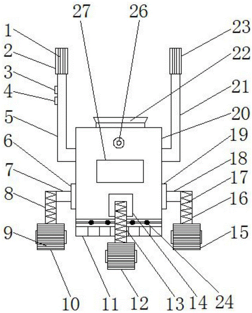
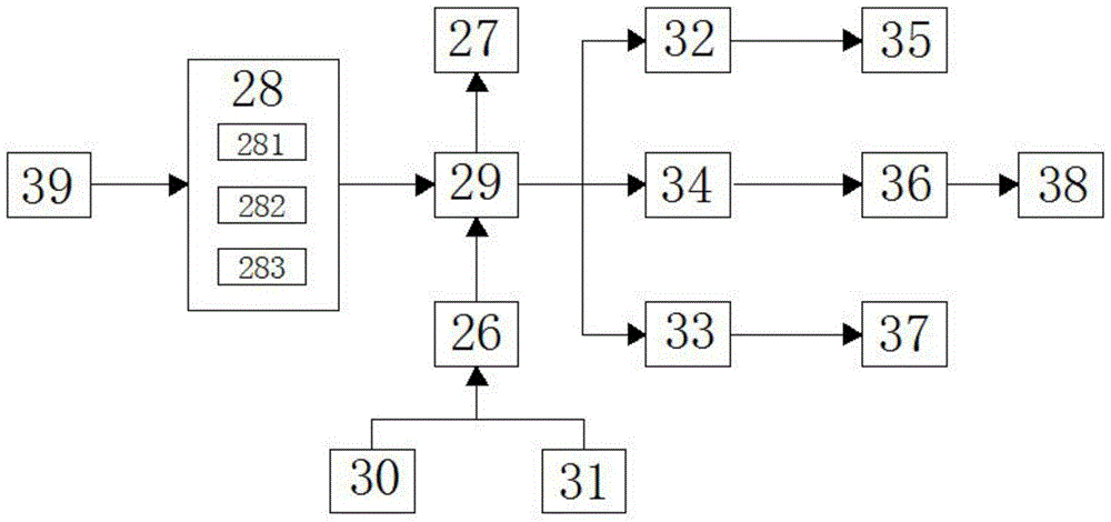
[0017] see Figure 1-3 , the present invention provides a technical solution: a mobile grouting device for building construction, comprising a grouting box 20, the bottom of the grouting box 20 is provided with a grout leakage hole 11, and the inside of the grouting box 20 is provided with a rotary bearing 24, And the both sides of rotary bearing 24 are all provided with leaf door 25, by offering the slurry leakage hole 11 at the bottom of laying box 20, rotar...


PUM


Abstract

The invention discloses a mobile mortar laying device for building construction, which belongs to the technical field of building equipment. The mobile mortar laying device for building construction comprises a mortar laying box; the bottom part of the mortar laying box is provided with mortar leaking holes; the mortar laying box is internally provided with a rotation bearing; two sides of the rotation bearing are provided with page doors; the front surface of the mortar laying box is provided with a first fixing block; the upper side of the first fixing block is provided with a display screen; the upper side of the display screen is provided with a high-definition camera; the high-definition camera is electrically connected with an infrared sensor, an orientation sensor and a central processor respectively; the central processor is electrically connected with the display screen and an ingredient detection unit respectively. According to the mobile mortar laying device for building construction, intelligent and full automatic mortar laying can be carried out, the quality of the mortar ingredient inside the mortar laying device can be detected, the mortar laying process is quick and accurate, material is divided uniformly, mortar laying is quick, the labor intensity is small, mortar laying is uniform, the mortar laying efficiency is high, and safety and stability are high.

Description

technical field [0001] The invention relates to the technical field of grouting devices, in particular to a mobile grouting device for building construction. Background technique [0002] In the field of construction, the grouting device is one of the indispensable construction equipment. At present, some existing grouting devices on the market cause waste of mortar in the construction technology. The grouting method in the traditional technology is generally manual operation. Put the mortar into the grouting box with a grout shovel, and then spread the mortar evenly with a shovel. It is impossible to realize intelligent and fully automatic grouting work, and it cannot Controlling the quality of mortar ingredients inside the grouting device, this method is labor-intensive, it is difficult to guarantee the uniformity of manual grouting, the efficiency of grouting is low, and it requires high technology and proficiency of workers. During use, due to the wheels of the general ...

Claims


Application Information

Patent Timeline
Patent Type & Authority Patents(China)
IPC IPC(8): E04G21/20
Inventor 张启志高瞻赵中强杨晨张俊伊庆刚琚花花张雪岭吕二文
Owner 鄄城县舜德董氏食品有限公司
Learn More