Clamping device and method for thin-walled frame type parts
A clamping device and parts technology, which is applied in the field of processing clamping devices for thin-walled frame parts, can solve the problems of difficult control of clamping force, machining accuracy error, high cost, etc., and achieve stability, flexible operation, and size applicability strong effect
- Summary
- Abstract
- Description
- Claims
- Application Information
AI Technical Summary
Problems solved by technology
Method used
Image
Examples
Embodiment 1
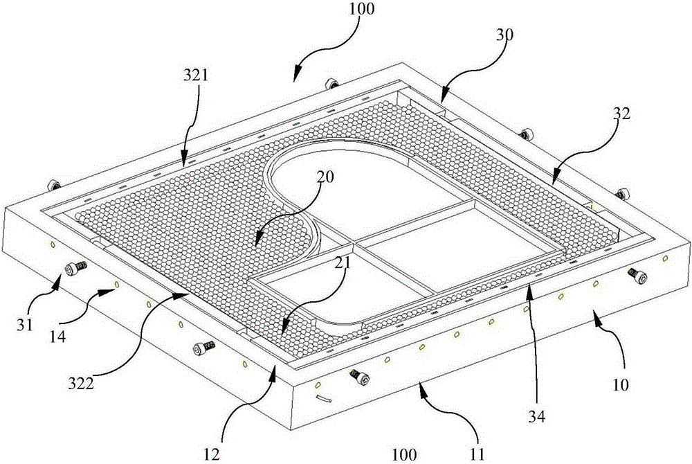
[0039] figure 1 It is a structural schematic diagram of the clamping device for the thin-walled frame parts of this embodiment
[0040] figure 2 It is a schematic diagram of the bottom plate of the clamping device and the internal electromagnet of the thin-walled frame parts of this embodiment
[0041] like figure 1 , as shown in 2, the clamping device 100 for thin-walled frame parts includes: a bottom plate portion 10 and a position limiting portion 20 disposed in the bottom plate portion and a clamping portion 30 for clamping the position limiting portion 20 .
[0042] in:
[0043] Bottom plate portion 10 is the groove shape of top opening, is rectangular, is used for accommodating parts to be processed, comprises bottom 11 and side 12, and its bottom 11 is hollow, and electromagnet 13 is arranged in it, is used for generating magnetic force after electrification, will The electromagnet is installed in the hollow part of the bottom plate part 10 to insulate and ensure s...
Embodiment 2
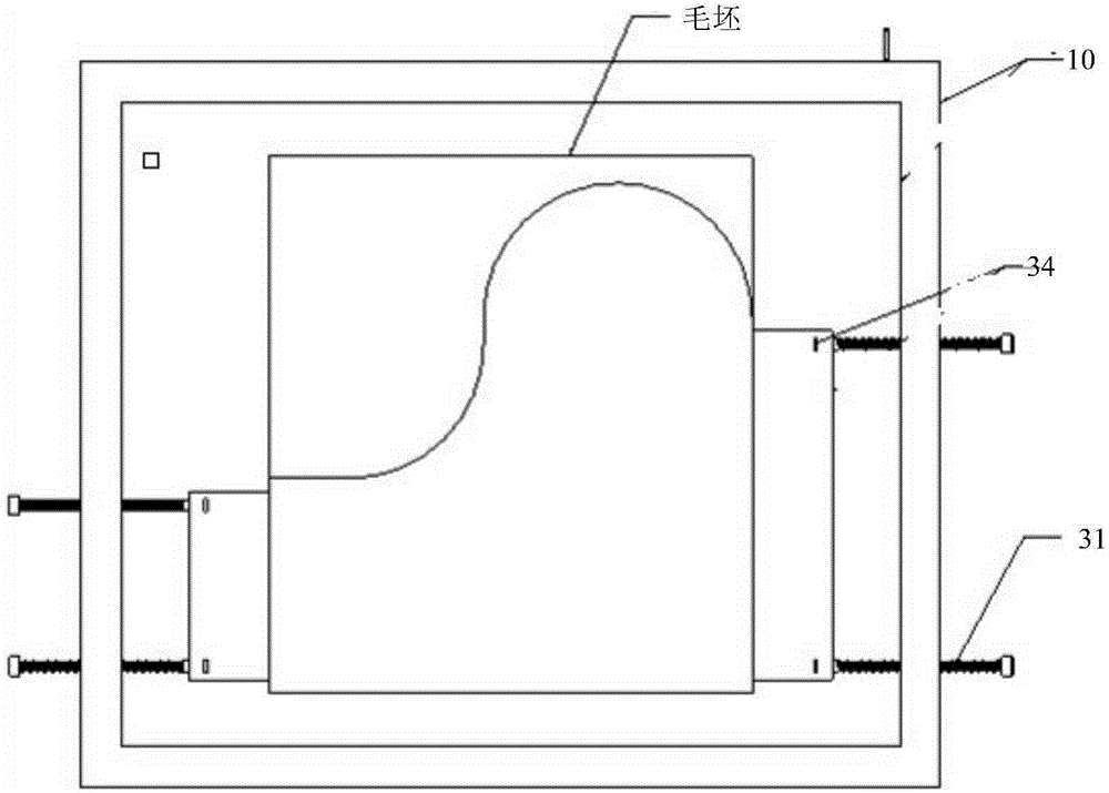
[0064] image 3 Schematic diagram of clamping for rough machining using the clamping device for thin-walled frame parts of the above embodiment
[0065] The process of clamping and processing on the processing machine using the clamping device for thin-walled frame parts in the above-mentioned embodiment 1 will be described in detail below.
[0066] Such as image 3 As shown, the blank of the rectangular thin plate part is clamped on the clamp body: the lower end surface of the blank is in contact with the upper end surface of the backing plate 33, and the lower end surface of the backing plate 33 is in contact with the upper end surface of the bottom plate part 10 (with an electromagnet inside), and the blank passes through the stress. The measuring filler block 34 and the clamping rod 31 screw clamp the end faces on both sides to fix (that is, at this time, the two sets of sliding push plates 321 and the two sets of fixed push plates 322 have been disassembled), and the cla...
PUM
 Abstract
Description
Claims
Application Information
 - R&D
- Intellectual Property
- Life Sciences
- Materials
- Tech Scout
- Unparalleled Data Quality
- Higher Quality Content
- 60% Fewer Hallucinations
Browse by: Latest US Patents, China's latest patents, Technical Efficacy Thesaurus, Application Domain, Technology Topic, Popular Technical Reports.
© 2025 PatSnap. All rights reserved.Legal|Privacy policy|Modern Slavery Act Transparency Statement|Sitemap|About US| Contact US: help@patsnap.com


