A power-on surge current suppression circuit applied to switching power supply

A surge current, suppressing circuit technology, applied in electrical components, output power conversion devices, etc., can solve the problems of reducing the reliability of AC-DC converters, large power consumption of NTC resistors, and high cost

Inactive Publication Date: 2017-10-31
GUANGDONG UNIV OF TECH
View PDF7 Cites 0 Cited by
  • Summary
  • Abstract
  • Description
  • Claims
  • Application Information

AI Technical Summary

Problems solved by technology

For example, the cost of connecting NTC thermistors in series is the lowest, but the AC input current always flows through the thermistors during normal operation, resulting in high power consumption of NTC resistors, which are in high temperature and high current state for a long time, and what is more serious is after power failure. You must wait for the NTC resistor to cool down to normal temperature before powering on, otherwise the thermistor will lose its ability to suppress the surge current, reducing the reliability of the AC-DC converter; the AC zero-crossing trigger method requires a silicon controlled rectifier device, In addition, auxiliary power supply and AC zero-crossing detection circuit need to be added, which are costly and complicated; although the parallel connection of power resistor and relay can better solve the contradiction between the magnitude of the startup surge current and the power consumption of the current-limiting resistor during normal operation, but The relay has a large pull-in current, poor reliability of mechanical contacts, and large volume

Method used


Image

  • A power-on surge current suppression circuit applied to switching power supply
  • A power-on surge current suppression circuit applied to switching power supply
  • A power-on surge current suppression circuit applied to switching power supply

Examples


Embodiment 1

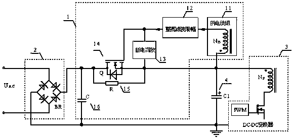
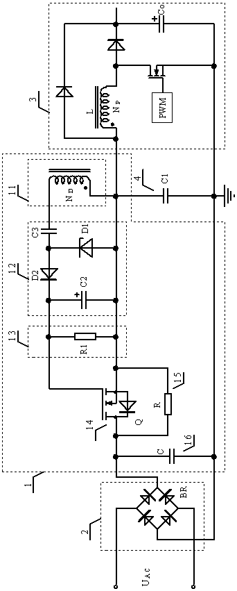
[0019] A power-on surge current suppression circuit 1 applied to switching power supplies, such as figure 2 As shown, the rectifying, filtering and limiting circuit 12 includes a coupling capacitor C3, a high frequency rectifying diode D2, a voltage stabilizing diode D1 and a filtering capacitor C2. Both ends of the filter capacitor C2 are respectively connected to the gate and source of the N-channel MOS transistor 14, the anode of the high-frequency rectifier diode D2 is connected to the cathode of the Zener diode D1, and the cathode of the high-frequency rectifier diode D2 is connected to the N-channel MOS transistor 14 connected to the gate, the anode of the Zener diode D1 is connected to the source of the N-channel MOS transistor 14; one end of the coupling capacitor C3 is connected between the high-frequency rectifier diode D2 and the Zener diode D1, and the other end is connected to the power supply winding 11 connected. Resistor R1 can be selected for the power-off b...

Embodiment 2

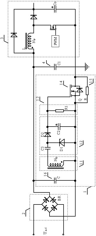
[0022] As a modification of Embodiment 1, such as image 3 As shown, in this embodiment, the power-on surge current suppression circuit 1 is connected to another position between the bridge rectifier 2 and the DC-DC converter 3, and the drain of the N-channel power MOS transistor 14 is connected to the DC-DC converter The common potential reference terminal of 3, that is, one end of the input filter capacitor C1, the source S is connected to the negative end of the bridge rectifier 2; and the main winding One end of the power supply winding 11 connected together with the ends of the same name is connected to the source of the N-channel MOS transistor 14, and the other end of the power supply winding 11 is connected to the input end of the rectification filter limiting circuit, and is connected to one end of the coupling capacitor C3.

Embodiment 3

[0024] A power-on surge current suppression circuit 1 applied to switching power supplies, such as Figure 4 As shown, the rectifying, filtering and limiting circuit 12 includes a voltage dividing and current limiting resistor R2, a high frequency rectifying diode D2, a voltage stabilizing diode D1, and a filtering capacitor C2. The cathode of the Zener diode D1 is connected to the gate of the N-channel MOS transistor 14 , and the anode of the Zener diode D1 is connected to the source of the N-channel MOS transistor 14 . Both ends of the filter capacitor C2 are respectively connected to the gate and source of the N-channel MOS transistor 14; the cathode of the high-frequency rectifier diode D2 is connected to the gate of the N-channel MOS transistor 14, and the anode of the high-frequency rectifier diode D2 is connected to the voltage divider One end of the current limiting resistor R2, and the other end of the voltage dividing current limiting resistor R2 is connected to the ...


PUM


Abstract

A power-on surge current suppression circuit applied to a switching power supply is disclosed. The power-on surge current suppression circuit comprises an optional small-capacity filter capacitor C, an N-channel MOS tube Q, a current suppression resistor R, an outage leakage circuit, a rectifying filtering amplitude-limiting circuit and a power supply winding; the two ends of the current suppression resistor R are connected with the drain electrode and the source electrode of the N-channel MOS tube Q; the outage leakage circuit is connected between the grid electrode and the source electrode of the N-channel MOS tube Q; the rectifying filtering amplitude-limiting circuit and the power supply winding are serially connected and then connected between the grid electrode and the source electrode of the N-channel MOS tube Q; the drain electrode and the source electrode of the N-channel MOS tube Q are serially connected between a power frequency rectifier and a DC-DC converter; and the optional small-capacity filter capacitor C is connected between the positive end and the negative end of the power frequency rectifier. The surge current in the power-on moment is limited by the power-on surge current suppression circuit; the MOS tube is low in power consumption and high in starting speed; and the power-on surge current suppression circuit is short in time for allowing re-power-on.

Description

technical field [0001] The present application relates to the technical field of switching power supplies, in particular to a power-on surge current suppression circuit applied to switching power supplies. Background technique [0002] In the AC-DC drive circuit, the alternating current is directly or indirectly filtered by a large capacitor after rectification. The voltage at the filter capacitor terminal rises from zero at the moment of power-on. If it is just near the maximum value of the sinusoidal alternating current when the power is turned on, there may be a transient high current of up to hundreds of amperes at the moment of power-on, which will affect the power grid and the AC-DC conversion in series. Devices in the input channel of the device, such as fuses, rectifier diodes, and power frequency filter capacitors, form a serious high-current impact. The magnitude and duration of the transient surge current are determined by factors such as the capacity of the filt...

Claims


Application Information

Patent Timeline
Patent Type & Authority Patents(China)
IPC IPC(8): H02M1/32H02M1/36
Inventor 潘永雄陈林海郑明治黄明旭徐思蔚
Owner GUANGDONG UNIV OF TECH
Why Eureka
Try Eureka