A relay protection circuit

A relay protection, relay technology, applied in emergency protection circuit devices, protection against overvoltage, circuit devices, etc., can solve problems such as device damage, VCC abnormality, and large starting inrush current.

Active Publication Date: 2022-05-27
深圳市瀚强科技股份有限公司
View PDF3 Cites 0 Cited by
  • Summary
  • Abstract
  • Description
  • Claims
  • Application Information

AI Technical Summary

Problems solved by technology

[0003] The existing analog block chain power supply products have a simple control logic for the relay at the input end. Only by detecting the control voltage VCC to control the pull-in and disconnection of the relay, this control logic has the following risks: VCC is abnormal, the relay is not pull-in, and the normal input Under normal circumstances, the main circuit is working, and the bus is loaded at this time, which will damage the slow-start resistor; in the hot engine state, repeated power-on and power-on operations without load, because the VCC voltage has not been released, the VCC voltage still exists, and the relay maintains the pull-in state at this time , the bus voltage is charged after starting up, resulting in a huge start-up inrush current, resulting in damage to the device

Method used


Image

  • A relay protection circuit
  • A relay protection circuit
  • A relay protection circuit

Examples


Embodiment Construction

[0029] The technical solutions in the embodiments of the present invention will be clearly and completely described below with reference to the accompanying drawings in the embodiments of the present invention. Obviously, the described embodiments are part of the embodiments of the present invention, but not all of the embodiments. Based on the embodiments of the present invention, all other embodiments obtained by those of ordinary skill in the art without creative efforts shall fall within the protection scope of the present invention.

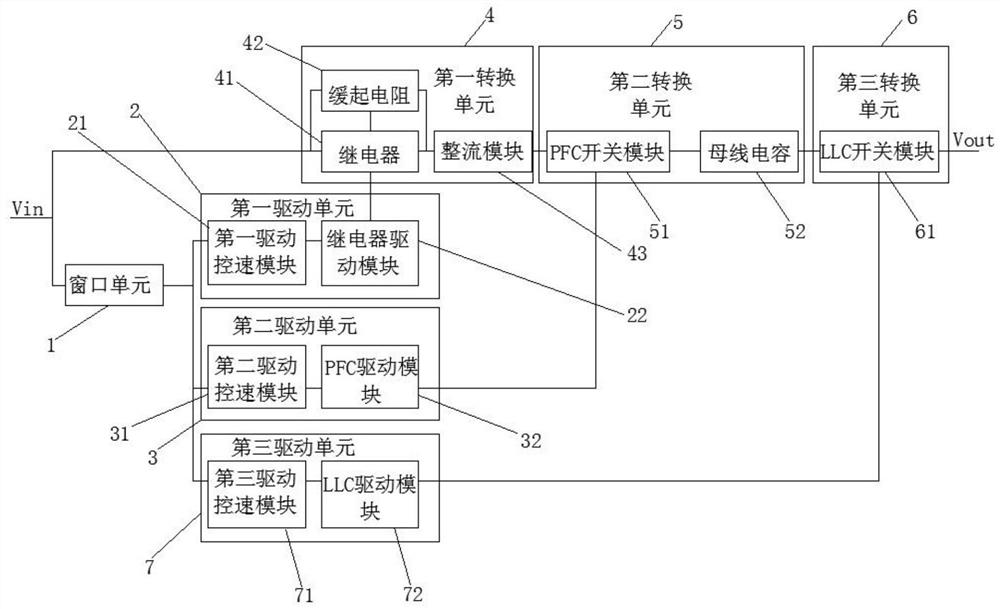
[0030] refer to figure 1 , showing a circuit schematic diagram of a relay protection circuit provided by the present invention. Specifically, it is used to accurately control the output of the circuit and protect the output circuit according to the range of the input voltage, including a control module and a conversion module, and the control module includes a window unit 1 , a first driving unit 2 and a second driving unit 3 ;

[0031] Th...


PUM


Abstract

The invention provides a relay protection circuit, including a control module and a conversion module, the control module includes a window unit, a first drive unit and a second drive unit; the conversion module includes a first conversion unit, a second conversion unit and The third conversion unit, the first drive unit includes a first drive speed control module and a relay drive module, the first drive speed control module outputs the first control signal to the relay of the first conversion unit by controlling the relay drive module; the second drive unit includes The second drive speed control module and the PFC drive module, the second drive speed control module outputs the second control signal to the PFC switch module of the second conversion unit by controlling the PFC drive module; the input end of the first conversion unit is connected to one end of the window unit The other end of the window unit outputs control signals to the first drive speed control module and the second drive speed control module. The improved circuit can limit the start-up inrush current and improve product reliability.

Description

technical field [0001] The invention relates to the technical field of relays, in particular to a relay protection circuit. Background technique [0002] Relay is a control switch that controls strong electric signals through weak electric signals, so it is widely used in the field of industrial control. [0003] The existing analog block chain power supply products have simple control logic for the relay at the input end. They only control the pull-in and break-off of the relay by detecting the control voltage VCC. This control logic has the following risks: VCC is abnormal, the relay is not pulled in, and the input is normal. Under the condition that the main circuit is working, the busbar is loaded at this time, which will damage the start-up resistor; in the warm-up state, the power-on and power-on operations are repeated with no load. Since the VCC voltage is not released, the VCC voltage still exists, and the relay maintains the pull-in state at this time. , the bus v...

Claims


Application Information

Patent Timeline
Patent Type & Authority Patents(China)
IPC IPC(8): H02H7/20H02H3/20
CPCH02H7/20H02H3/207
Inventor 黎文权王绍煦陈亚梯王少用
Owner 深圳市瀚强科技股份有限公司
Why Eureka
Try Eureka