Device and method for continuously manufacturing metal powder through multi-electrode plasma arcs
A plasma arc and metal powder technology, which is applied in the field of high melting point refractory metals and multi-component alloyed powders, achieves the effects of good powder roundness, reduced powder manufacturing costs, and low oxygen and inclusion content
- Summary
- Abstract
- Description
- Claims
- Application Information
AI Technical Summary
Problems solved by technology
Method used
Image
Examples
Embodiment 1
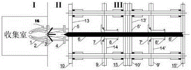
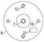
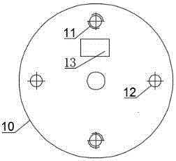
[0041] Such as Figure 5-7 As shown, 1. During production, first fill inert gas at the protective gas inlet 4, empty the air inside the nozzle 1 of the expansion chamber, and then start the plasma arc generator electrode 3. The plasma arc generator electrode 3 is a non-transferred arc, a total of three groups , wherein the angle between the two groups of electrodes below is 115°, and the angle between the other two groups is 122.5°. Generally, the adjustable output current range is 20 amperes, and the temperature of plasma arc generator electrode 3 is 8000°C; the outlet angle of nozzle 1 in the expansion chamber is 5°, the inner diameter of the outlet end section D 1 At 15 mm, the arc radius r is at 10 mm, and the middle section of the outlet is D 2 At 10 mm, the arc radius R is at 50 mm, and the front section of the exit is D 3 At 100mm, the total nozzle length is at 180mm.
[0042] 2. After completing step 1, start the moving flange 9' and the raw material rod clamp 7' of...
Embodiment 2
[0052] Such as Figure 5-7 As shown, 1. During production, first fill inert gas at the inlet of the protective gas, empty the air inside the nozzle of the expansion chamber, and then start the electrodes of the plasma arc generator. The electrodes of the plasma arc generator are three groups of non-transferred arcs, and the included angle is 120°, the general adjustable output current range is 100 amperes, the electrode temperature of the plasma arc generator is 13000°C; the outlet angle of the expansion chamber nozzle is 75°, and the inner diameter of the end section of the outlet is D 1 At 190 mm, the arc radius r is at 130 mm, and the middle section of the outlet is D 2 At 50 mm, the arc radius R is at 350 mm, and the front section of the exit is D 3 At 900 mm, the total nozzle length is at 1500 mm.
[0053] 2. After completing step 1, start the moving flange of the second set of propellers of the feeding device and the raw material rod clamp. The raw material rod clamp c...
Embodiment 3
[0062] Such as Figure 5-7 As shown, 1. During production, first fill inert gas at the inlet of the protective gas, empty the air inside the nozzle of the expansion chamber, and then start the electrodes of the plasma arc generator. The electrodes of the plasma arc generator are non-transferred arcs in three groups, of which the following two The included angle of the electrodes is 115°, and the mutual included angle of the other two groups is 122.5°. Generally, the adjustable output current range is 300 amperes, and the electrode temperature of the plasma arc generator is 30,000°C; the outlet angle of the expansion chamber nozzle is 45°, and the inner diameter of the end section of the outlet D. 1 At 100 mm, the arc radius r is at 100 mm, and the middle section of the outlet is D 2 At 30 mm, the arc radius R is at 150 mm, and the front section of the exit is D 3 At 250mm, the total nozzle length is at 500mm.
[0063] 2. After completing step 1, start the moving flange of t...
PUM
 Abstract
Description
Claims
Application Information
 - R&D
- Intellectual Property
- Life Sciences
- Materials
- Tech Scout
- Unparalleled Data Quality
- Higher Quality Content
- 60% Fewer Hallucinations
Browse by: Latest US Patents, China's latest patents, Technical Efficacy Thesaurus, Application Domain, Technology Topic, Popular Technical Reports.
© 2025 PatSnap. All rights reserved.Legal|Privacy policy|Modern Slavery Act Transparency Statement|Sitemap|About US| Contact US: help@patsnap.com


