
Progressive die of IP positioning bracket

A technology for positioning brackets and progressive dies, applied in metal processing equipment, forming tools, manufacturing tools, etc., can solve the problems of complex structure, low efficiency, relatively high operator quality requirements, save equipment space, improve production efficiency, Damage reduction effect

Inactive Publication Date: 2016-01-20
上海德真工贸有限公司
View PDF7 Cites 1 Cited by
  • Summary
  • Abstract
  • Description
  • Claims
  • Application Information

AI Technical Summary

Problems solved by technology

There are many styles of IP positioning brackets, and the structure is more complicated
In modern industrial production, IP positioning brackets often use single-process molds, which go through multiple single-process processes such as punching dies, falling dies, and bending dies. Due to the many processes involved and the high precision requirements, The cost of the single-process mold is high, the efficiency is low, the quality of the product is unstable, and the requirements for the quality of the operator are relatively high

Method used


Image

  • Progressive die of IP positioning bracket
  • Progressive die of IP positioning bracket

Examples


Embodiment Construction

[0018] In order to make the technical means, creative features, goals and effects achieved by the present invention easy to understand, the present invention will be further described below in conjunction with specific diagrams.

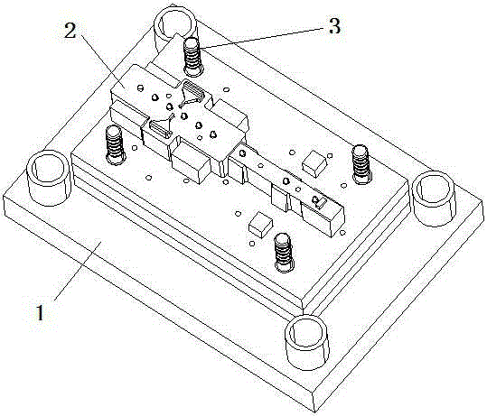
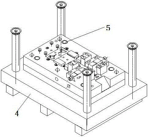
[0019] refer to figure 1 , figure 2 , IP positioning bracket progressive die, including an upper die 1, a lower die 4, a belt transport channel is set between the upper die 1 and the lower die 4, a plurality of stations are set on the material belt transport channel, and a plurality of stations Including bending station, waste cutting station, punching station;

[0020] The bending station includes a lower insert for bending and forming on the lower die 4, and an upper insert for bending and forming on the upper die 1;

[0021] The upper insert for bending and forming includes a long strip-shaped protrusion 2, the width of the front end of the protrusion 2 is greater than the width of the rear end, and there are at least two conical protrusions on...


PUM


Abstract

The invention relates to the die field, in particular to a progressive die. The progressive die of an IP positioning bracket comprises an upper die and a lower die, wherein a material strip transport corridor is arranged between the upper die and the lower die; a plurality of stations are arranged on the material strip transport corridor; the plurality of stations comprise a bending station, a waste cutting station and a punching station; the bending station comprises a lower insert block for folding and bending on the lower mould, and an upper insert block for folding and forming on the upper mould; the upper insert block for folding and forming comprises a long-strip-shaped bump; at least two conical bumps are arranged on the long-strip-shaped bump; and the conical bumps are arranged in the form of a straight line. According to the progressive die of the IP positioning bracket, the bending station, the punching station and the waste cutting station are arranged on one progressive die, so that three processes of bending, punching and waste cutting are realized; compared with a conventional single-process die, the progressive die is integrated, so that the production efficiency is improved while an equipment space is saved; meanwhile, the side surface of the strip-shaped bump is rounded off to reduce the possibility that a product is damaged during press-cutting.

Description

technical field [0001] The invention relates to the field of molds, in particular to progressive dies. Background technique [0002] In modern industrial production, complex auto parts are mainly produced by stamping dies. There are many styles of IP positioning brackets, and the structure is relatively complicated. In modern industrial production, IP positioning brackets often use single-process molds, which go through multiple single-process processes such as punching dies, falling dies, and bending dies. Due to the many processes involved and the high precision requirements, The cost of the single-process mold is high, the efficiency is low, the quality of the product is unstable, and the requirements for the quality of the operator are relatively high. Contents of the invention [0003] The object of the present invention is to provide an IP positioning bracket progressive die to solve the above technical problems. [0004] The technical problem solved by the pres...

Claims


Application Information

Patent Timeline
Patent Type & Authority Applications(China)
IPC IPC(8): B21D37/10
CPCB21D37/10
Inventor 金华陆耀明
Owner 上海德真工贸有限公司
Learn More