


Quick Research
Generate reliable direction feasibility study reports for your R&D in just a few steps.

Technical Q&A
Discover and master advanced knowledge NOW. Basics, ideas, possibilities, all at once.

Find Solutions
As an expert in R&D theories, this can generate solutions to your technical problems instantly.

Evaluate Feasibility
Analyze your overall solution with one click, know your potential R&D risks in advance.

Monitor Landscape
Get weekly tech updates, stay abreast of the latest tech innovations and key insights.
Control system for internal combustion engine
A technology for control systems and internal combustion engines, applied in engine control, fuel injection control, internal combustion piston engines, etc., can solve problems such as increased combustion noise and pressure rise, and achieve the effect of suppressing misfires
- Summary
- Abstract
- Description
- Claims
- Application Information
AI Technical Summary
Problems solved by technology
Method used
Image

Examples
Embodiment 1
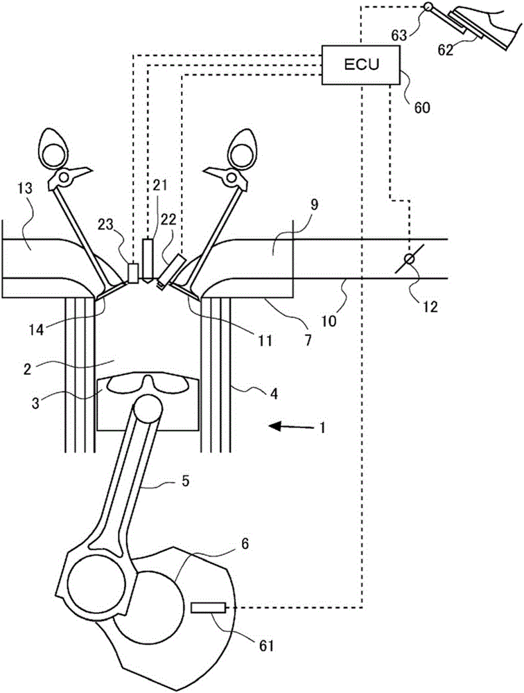
[0044] figure 1 It is a diagram for explaining the system configuration of this embodiment. In this embodiment, an internal combustion engine 1 is provided. The internal combustion engine 1 is a gasoline engine. figure 1 Only one cylinder of the plurality of cylinders 2 is shown in . The internal combustion engine 1 is mounted on a vehicle, for example.
[0045] The internal combustion engine 1 includes a cylinder block 4 , and the cylinder block 4 has a piston 3 inside. Piston 3 is connected to crankshaft 6 via connecting rod 5 . A crank angle sensor 61 is provided near the crankshaft 6 . The crank angle sensor 61 detects the rotation angle of the crankshaft 6 (that is, the crank angle).
[0046] A cylinder head 7 is assembled on top of the cylinder block 4 . The cylinder head 7 has an intake port 9 communicating with the inside of the cylinder 2 . In addition, an intake pipe 10 is connected to the cylinder head 7 . The intake port 9 communicates the intake pipe 10 w...
Embodiment 2
[0079] In this embodiment, when the pressure in the cylinder 2 rises sharply during the fuel injection for diffusion combustion, the fuel injection is stopped midway. That is, the main injection is stopped halfway. Since other devices and the like are the same as those in Embodiment 1, description thereof will be omitted.
[0080] Here, when the pressure in the cylinder 2 rises sharply at the time of fuel injection for diffusion combustion, it is considered that homogeneous charge compression ignition occurs. In this case, if fuel injection continues, it will cause a further pressure rise. Therefore, in the present embodiment, when the increase rate (increase amount per unit time) of the pressure in the cylinder 2 is equal to or greater than a predetermined rate, even in the middle of the fuel injection for diffusion combustion, the fuel is injected stop.
[0081] Figure 5 It is a graph showing the relationship between the fuel injection timing and the ignition timing acc...
Embodiment 3
[0092] In the present embodiment, the fuel injection timing in the diffusion combustion of the next cycle is determined based on the time point when the pressure in the cylinder 2 becomes maximum during the diffusion combustion. Since other devices and the like are the same as those in Embodiment 1, description thereof will be omitted.
[0093] In the present embodiment, the fuel injection timing of the next cycle is adjusted so that the time point at which the pressure in the diffusion combustion of the next cycle becomes the maximum becomes the time point at which the combustion efficiency becomes higher. Therefore, the fuel injection timing in the next cycle is adjusted so that the difference between the time point when the pressure becomes the maximum in the current cycle and the time point when the pressure becomes the maximum when the combustion efficiency is the highest is eliminated.
[0094] Figure 7 It is a graph showing the relationship between the fuel injection ...
PUM
 Abstract
Description
Claims
Application Information
 - R&D Engineer
- R&D Manager
- IP Professional
- Industry Leading Data Capabilities
- Powerful AI technology
- Patent DNA Extraction
Browse by: Latest US Patents, China's latest patents, Technical Efficacy Thesaurus, Application Domain, Technology Topic, Popular Technical Reports.
© 2024 PatSnap. All rights reserved.Legal|Privacy policy|Modern Slavery Act Transparency Statement|Sitemap|About US| Contact US: help@patsnap.com