Eureka AIR delivers breakthrough ideas for toughest innovation challenges, trusted by R&D personnel around the world.

Method and system for position estimation of switched reluctance motor on the basis of pulse current envelope

A switched reluctance motor, pulse current technology, applied in the direction of electronic commutation motor control, control system, electrical components, etc., can solve the problems of large inductance change rate, negative torque generation, etc., to achieve simple algorithm, increase motor starting speed. Moment and versatility

Active Publication Date: 2016-01-13
佛山伺达控自动化科技有限公司
View PDF5 Cites 11 Cited by
  • Summary
  • Abstract
  • Description
  • Claims
  • Application Information

AI Technical Summary

Problems solved by technology

The advantage of injecting high-frequency pulses into the previous non-conducting phase is that it is simple and easy to implement, but the disadvantage is that it will generate negative torque
The advantage of the method of injecting high-frequency pulses into the latter non-conducting phase is that the accuracy of motor commutation is improved, and the commutation position is at the moment when the inductance just rises, the inductance change rate is large, and the peak value of the pulse current is also very large, which is easy for the microprocessor The disadvantage is that during the pulse injection process, the pulse current is in a symmetrical state with the minimum center position of the inductance. In this way, it is necessary to judge the direction of the pulse current amplitude change during the commutation process in order to finally judge the commutation time.
The advantage of this method is that it does not need to set the current threshold and is not affected by voltage and load fluctuations. It has certain robustness, but the influence of motor saturation needs to be considered.

Method used


Image

  • Method and system for position estimation of switched reluctance motor on the basis of pulse current envelope
  • Method and system for position estimation of switched reluctance motor on the basis of pulse current envelope
  • Method and system for position estimation of switched reluctance motor on the basis of pulse current envelope

Examples


Embodiment Construction

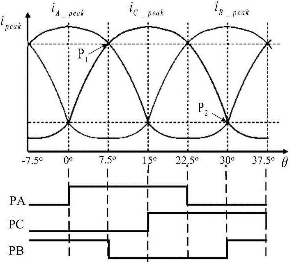
[0027] Such as figure 1 As shown, the position estimation method of the switched reluctance motor based on the pulse current envelope of the present invention comprises the following steps:

[0028] Step 1, set the frequency and duty cycle of the high-frequency PWM pulse signal injected into the non-conducting region, and the upper limit of the chopping current i in the chopper control method of the conducting region * And the value of the fixed fall time Δt, and the high level time of the high-frequency PWM pulse signal is equal to the fixed fall time Δt;

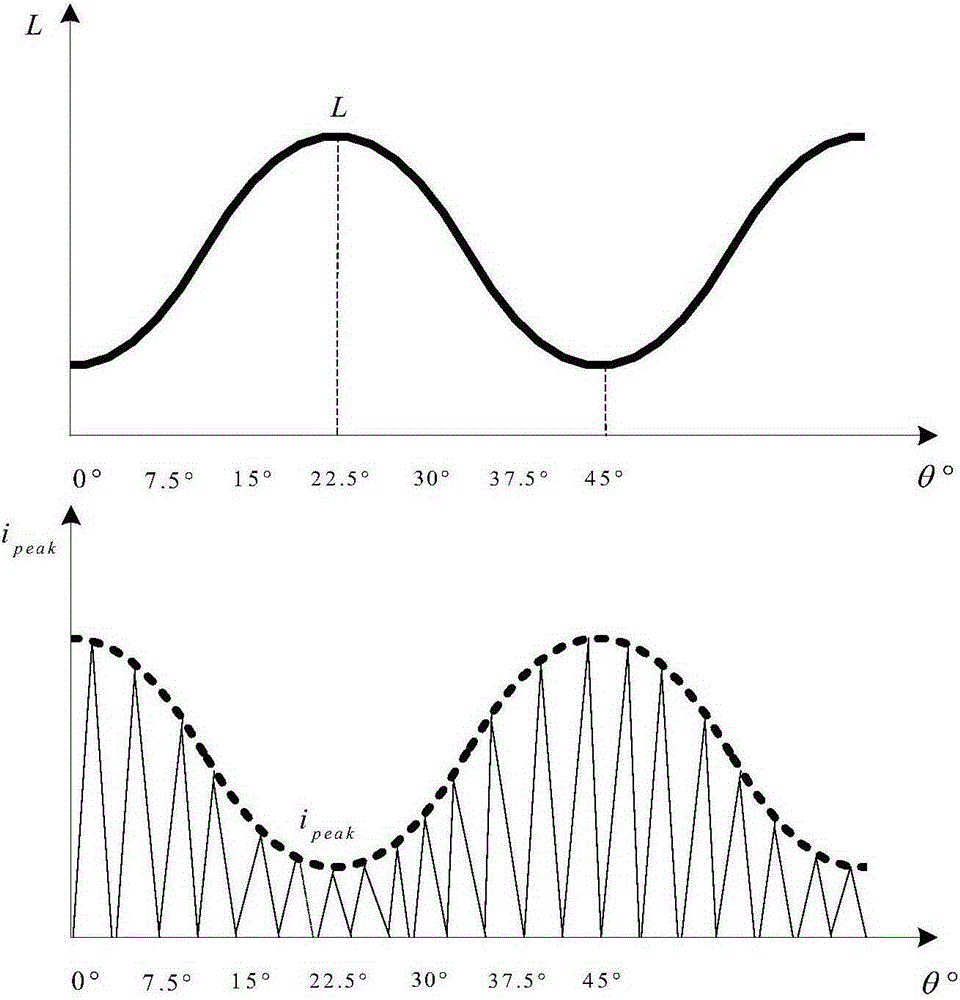
[0029] Step 2, in the non-conducting area, send a high-frequency PWM pulse signal control signal to the switching tube on the non-conducting phase, and read the peak value i of the pulse current collected on the falling edge of the high-frequency PWM pulse signal peak , the peak value of the pulse current is inversely proportional to the phase inductance value of the position, and then use each peak value i of the pulse c...


PUM


Abstract

The present invention discloses a method and system for position estimation of a switched reluctance motor on the basis of a pulse current envelope, belonging to the field of the switched reluctance motor control technique. The method for position estimation of the switched reluctance motor on the basis of the pulse current envelope comprises: performing initialization setting, extracting a pulse current envelope of a non-conducting region, extracting a pulse current envelope of a conducting region, extracting a complete period pulse current envelope, and determining positions, etc. The system for position estimation of the switched reluctance motor on the basis of the pulse current envelope comprises: an initialization module, a module of extracting a pulse current envelope of a non-conducting region, a module of extracting a pulse current envelope of a conducting region, a module of extracting a complete period pulse current envelope, and a position determination module. The method and system for position estimation of a switched reluctance motor on the basis of a pulse current envelope are simple, are capable of effectively estimating a position of a motor rotor, and are high in versatility, with no need for additional hardware.

Description

technical field [0001] The invention relates to a method and system for estimating the position of a switched reluctance motor, in particular to a method and system for estimating the position of a switched reluctance motor based on a pulse current envelope. Background technique [0002] In the application field, the switched reluctance motor needs the rotor position signal. At present, the rotor position signal is mainly obtained by the direct position detection method. This method is to add a position sensor to the motor to obtain the position signal. Typical examples include electromagnetic type and photoelectric type. , magnetosensitive, etc., among which photoelectric sensors are the most widely used, but these traditional mechanical sensors have complex structures and are inconvenient to install, which not only increases the complexity of the system structure, but also reduces the reliability of the system and increases the cost, restricting the Switched reluctance mot...

Claims


Application Information

Patent Timeline
IPC IPC(8): H02P6/185
Inventor 张磊兴志孙刚
Owner 佛山伺达控自动化科技有限公司
Why Eureka
Eureka Blog
Learn More