
Natural gas thermal treatment furnace

A heat treatment furnace, natural gas technology, applied in the direction of waste heat treatment, furnace, furnace type, etc., can solve the problems of uneven heating, high cost, increased energy consumption, etc., achieve good heat insulation performance, long service life, and reduce consumption Effect

Active Publication Date: 2016-01-13
山东新达重工机械有限公司
View PDF5 Cites 0 Cited by
  • Summary
  • Abstract
  • Description
  • Claims
  • Application Information

AI Technical Summary

Problems solved by technology

[0004] The existing heat treatment furnace has the following defects: 1. Uneven heating, high energy consumption, low thermal efficiency, and poor safety; 2. Low degree of automation and high labor intensity; 3. Heavy equipment and high cost will further increase energy consumption

Method used


Image

  • Natural gas thermal treatment furnace
  • Natural gas thermal treatment furnace

Examples


Embodiment Construction

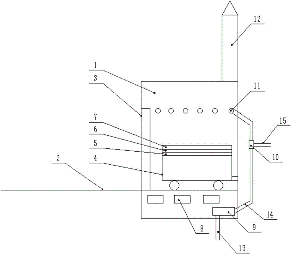
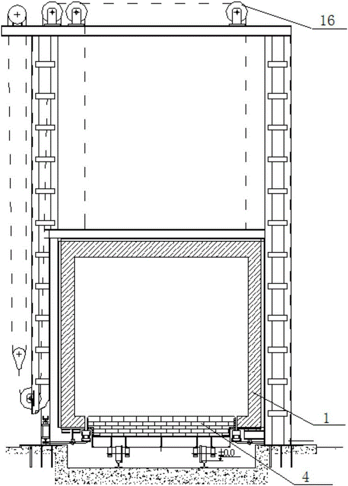
[0023] Such as Figure 1-Figure 2 As shown, the natural gas heat treatment furnace includes a furnace body 1, a furnace door 3 is provided on the front side of the furnace body 1, a horizontal guide rail 2 is provided at the bottom of the furnace body 1, the horizontal guide rail 2 extends to the outside of the furnace body, and a trolley is provided on the guide rail 2 4. Refractory parts are laid on the trolley 4; three flue openings 8 are evenly arranged on the side wall of the bottom of the furnace body 1; Three flue openings are set, which overcomes the overheating defect of the side flue openings.

[0024] An air displacer 9 is arranged in the flue at the bottom of the furnace body 1, and the intake pipe 13 of the air displacer 9 is used for cold air to enter. The outlet pipeline 14 of the air displacer 9 is connected to the burner 11 at the side of the furnace body 1 . The air outlet pipeline 14 that the air displacer 9 communicates with the burner 11 is also connecte...


PUM


Abstract

The invention discloses a natural gas thermal treatment furnace. The natural gas thermal treatment furnace comprises a furnace body; a furnace door is arranged on the front side of the furnace body; a horizontal guide way is arranged at the bottom of the furnace body and extends to the outside of the furnace body; a trolley is arranged on the horizontal guide way; a fire-resistant part is laid on the trolley; a plurality of flue outlets are uniformly formed in the side wall of the bottom of the furnace body; an air replacer is arranged in a flue of the bottom of the furnace body; cold air enters through an air inlet pipeline of the air replacer; the cold air is preheated through flue waste heat by the air replacer to form hot air which is then discharged through an air outlet pipeline of the air replacer; the air outlet pipeline of the air replacer is communicated to the positions of burners of the side of the furnace body. The left and right sides are both provided with the burners, so that defects of non-uniform heating caused by few burners and insecurity and high energy consumption caused by excessively large flow of each burner are overcome; the air replacer is added so that the air can be preheated through flue waste heat; natural gas and the hot air are mixed through a proportional valve, and compared with manual adjustment, the adjustment is more automatic and the efficiency is higher.

Description

technical field [0001] The invention relates to a natural gas heat treatment furnace. Background technique [0002] The heat treatment furnace occupies an extremely important position in the heat treatment process of the machinery manufacturing industry. It is an indispensable equipment to ensure product quality, improve machine performance, and prolong machine life. [0003] Modern heat treatment (especially chemical heat treatment) processes are becoming more and more complex, and there are many forms of heat treatment furnaces. For a continuous heat treatment process, a suitable continuous heat treatment furnace must be equipped; for a periodic heat treatment process, a forced circulation control atmosphere should be used to mechanize and automate the operation of the furnace. In the rapid development of machinery manufacturing and equipment manufacturing industries, it is particularly prominent to improve the thermal efficiency of heat treatment furnaces, reduce energy ...

Claims


Application Information

Patent Timeline
Patent Type & Authority Applications(China)
IPC IPC(8): F27B9/26F27B9/30F27D17/00
CPCY02P10/143
Inventor 曹宗安葛雪洁庞晓东
Owner 山东新达重工机械有限公司
Learn More