
Manufacturing technology for bent LED filament and bulb with bent LED filament

A technology of LED filament and manufacturing process, which is applied to the components of lighting devices, semiconductor devices of light-emitting elements, lighting devices, etc., and can solve problems such as difficulty in making various curved shapes

Inactive Publication Date: 2016-01-13
汤雄
View PDF6 Cites 12 Cited by
  • Summary
  • Abstract
  • Description
  • Claims
  • Application Information

AI Technical Summary

Problems solved by technology

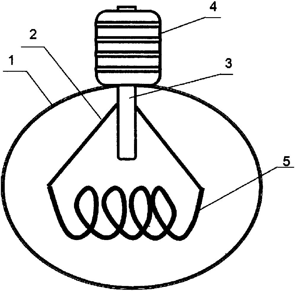
From the perspective of the current filament manufacturing technology, it is very common to make tungsten wires into curved shapes. This is because tungsten wires have no other ingredients except tungsten, and tungsten wires are flexible metals. Therefore, as long as different bending tools are used to make It is not a problem to bend into any shape, but the LED filament is not made of a single material, and usually requires complex crystal bonding on flexible metal or resin materials. Due to this limitation, it is easier to make the LED filament into a straight wire. It is very difficult to make various bending shapes. Judging from the current market, there is no technology that can bend the LED filament and use it.

Method used


Image

  • Manufacturing technology for bent LED filament and bulb with bent LED filament
  • Manufacturing technology for bent LED filament and bulb with bent LED filament
  • Manufacturing technology for bent LED filament and bulb with bent LED filament

Examples


Embodiment Construction

[0031] The present invention will be described in further detail below in conjunction with the accompanying drawings and specific embodiments.

[0032] The present invention firstly discloses the manufacturing process of curved LED filament, including the following steps:

[0033] (1) On a piece of flexible metal plate or resin plate, use a circuit drawing machine to describe a spiral circuit; the flexible metal plate mentioned in the present invention can be any metal material plate with flexible characteristics;

[0034] (2) Die-bonding is performed on the front and back sides of the spiral circuit that has been drawn; the die-bonding mentioned in the present invention is also called DieBond or chip mounting, and the die-bonding is through colloid (generally conductive for LEDs). glue or insulating glue) to bond the chip to the designated area of ​​the bracket to form a thermal path or an electrical path, which provides conditions for the subsequent wiring connection.

[00...


PUM


Abstract

The invention discloses a manufacturing technology for a bent LED filament and a bulb with the bent LED filament. The manufacturing technology mainly includes the steps that a spiral circuit is mechanically carved on a flexible metal plate or a resin plate through a circuit carving machine, then crystallization is conducted on a front face and a back face, and crystallization is conducted on the upper side and the lower side of a flexible metal wire or a line-shaped resin wire; and secondly, a corresponding bent die is used for manufacturing the flexible metal wire or the line-shaped resin wire into a bent LED light-emitting bar. The invention further discloses a bulb with the bent LED filament. The bulb is internally connected with the bent LED light-emitting bar. The bent LED light-emitting bar can be conveniently produced, and all original lamp manufacturing devices can be used on the new technology at the same time. The manufactured LED bulb is higher in wattage and more even in brightness than a straight bar type LED filament, and the radiating effect of the LED bulb is good. The power output of the LED bulb in the same glass-bulb cavity can be improved, and the same effect can be achieved by the LED bulb like traditional 100w bulbs and 12w LED bulbs with the same color temperature (2400 k) as the traditional bulbs.

Description

technical field [0001] The invention relates to the field of LED lighting fixtures, in particular to a manufacturing process for curved LED filaments and a light bulb with curved LED filaments. Background technique [0002] With the popularization of energy-saving awareness, the use of LED lamps is becoming more and more popular. Due to the uniform light emission and good heat dissipation, straight LED filaments occupy an increasing share in the field of antique lamps and conventional lighting lamps. However, due to the limitation of the length of the straight LED filament, its wattage is also greatly limited. Although from a theoretical point of view, the bulb can be made bigger and longer, so that the straight LED filament can be made correspondingly. Long, but from the perspective of practical use, if it is too long and too big, it will lose its meaning. A good inspiration is that making the straight filament into a curved shape can greatly increase the length of the fil...

Claims


Application Information

Patent Timeline
IPC IPC(8): F21S2/00F21V19/00F21V23/06F21Y101/02
CPCF21K9/90F21V19/0015F21V23/06
Inventor 汤雄
Owner 汤雄
Learn More