
Column type control device for low power consumption valve of electric valve

A control device and low power consumption technology, which is applied in the direction of valve operation/release device, valve device, valve details, etc., can solve the problems that cannot meet the needs of automatic irrigation, the valve is not suitable for remote control, and the power consumption of electric valve is high. The effect of reducing the cost of remote control, light structure and small movement resistance

Inactive Publication Date: 2018-09-04
XINJIANG INST OF WATER RESOURCES & HYDRAULIC POWER
View PDF6 Cites 0 Cited by
  • Summary
  • Abstract
  • Description
  • Claims
  • Application Information

AI Technical Summary

Problems solved by technology

[0003] The present invention provides a column type control device for an electric valve with low power consumption, which overcomes the above-mentioned deficiencies in the prior art, and can effectively solve the problem of existing automatic irrigation The valves in the system are not suitable for remote control and cannot meet the needs of automatic irrigation, and the power consumption of the existing electric valves is high. It is difficult to pull wires and deploy power grids to power the electric valves.

Method used


Image

  • Column type control device for low power consumption valve of electric valve
  • Column type control device for low power consumption valve of electric valve
  • Column type control device for low power consumption valve of electric valve

Examples


Embodiment Construction

[0022] The present invention is not limited by the following examples, and specific implementation methods can be determined according to the technical solutions of the present invention and actual conditions.

[0023] In the present invention, for the convenience of description, the description of the relative positional relationship of each component is based on the description attached to the description. figure 1 For example, the positional relationship of front, rear, top, bottom, left, right, etc. is determined according to the layout direction of the drawings in the description.

[0024] Below in conjunction with embodiment and accompanying drawing, the present invention will be further described:

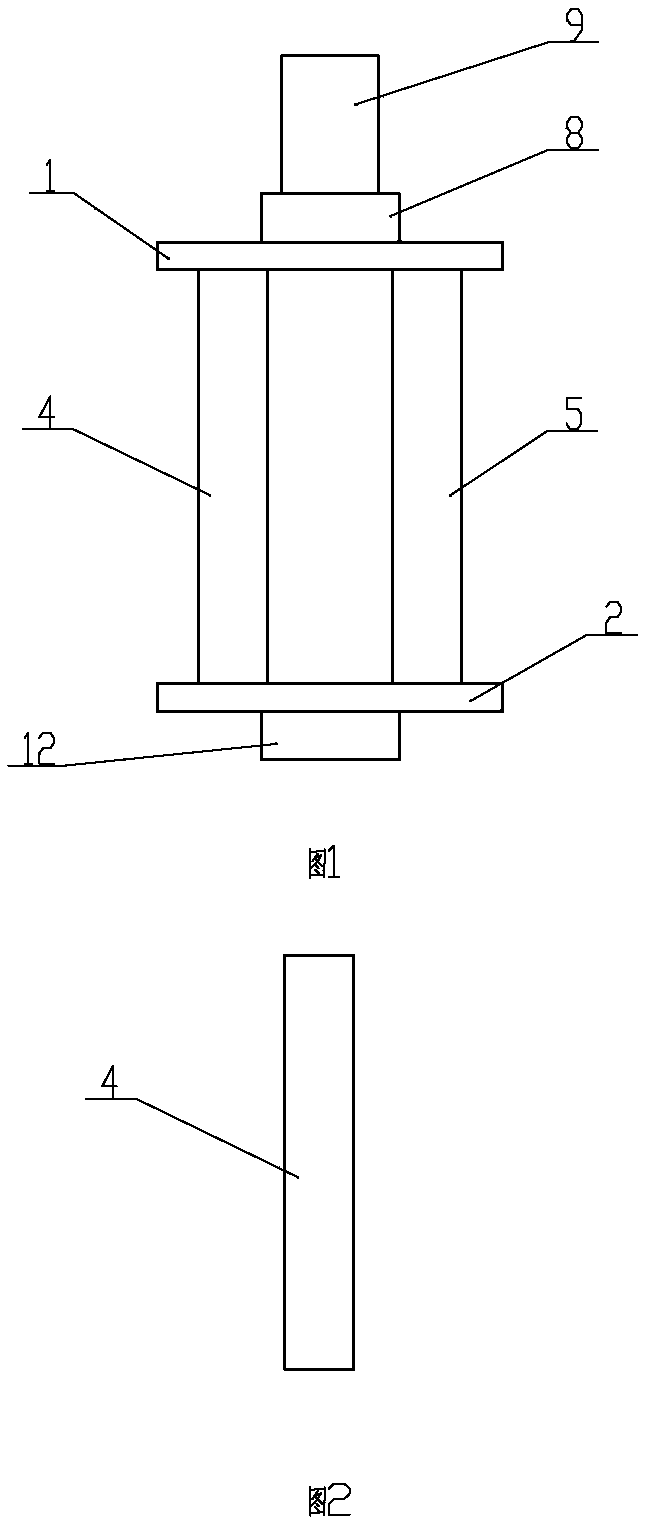
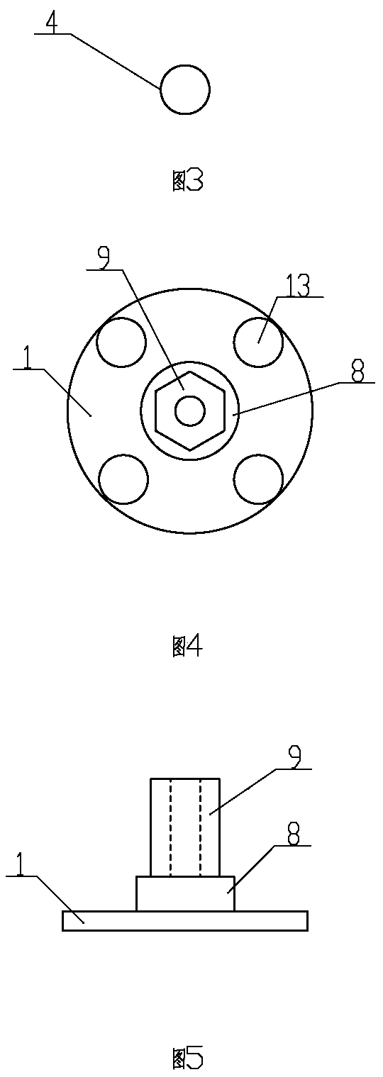
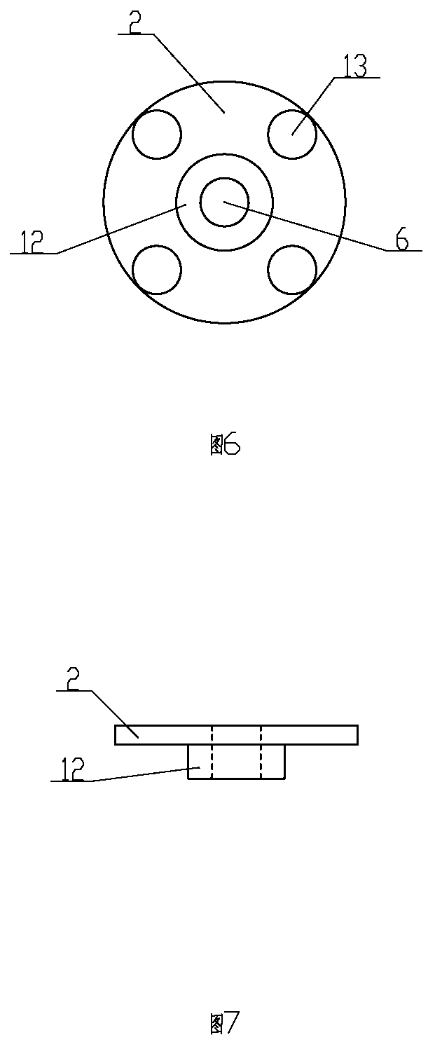
[0025] as attached figure 1 , 2 , 3, 4, 5, 6, 7, 8, and 9, the column control device of the electric valve low power consumption valve includes an upper connecting plate 1, a lower connecting plate 2 and a sliding block 3, and the upper connecting plate 1 and the lower con...


PUM


Abstract

The invention relates to the technical field of control valves and provides a columnar control device for an electric valve low-consumption valve. The columnar control device comprises an upper joint disc, a lower joint disc and a sliding block. A first supporting column, a second supporting column, a third supporting column and a fourth supporting column are arranged between the upper joint disc and the lower joint disc. The sliding block is arranged in a space defined by the supporting columns. A first connection structure is arranged on the sliding block. A second connection structure is arranged on the upper joint disc. A through hole is formed in the lower joint disc. The columnar control device is light and handy in structure and small in movement resistance and can be driven only through a motor small in power, such as a motor with the power being 1.5 watts. Compared with a traditional electric valve driven by a motor with the power being tens of watts, the electricity consumption is smaller, a smaller storage battery supplies power to the motor, no electric wire is needed, no wire grid needs to be distributed, remote control cost of automatic irrigation is lowered greatly, feasibility is high, and the columnar control device has the beneficial effects of being safe, easy, convenient to use, efficient and capable of saving manpower.

Description

technical field [0001] The invention relates to the technical field of electric valves, and relates to a column control device for electric valves with low power consumption. Background technique [0002] In modern agricultural production, automatic water-saving irrigation systems are gradually replacing manual irrigation. Due to low efficiency and waste of resources, manual irrigation can no longer meet the requirements of modern agricultural production methods. Traditional automatic water-saving irrigation systems are usually based on computers, etc. It consists of smart devices, humidity sensors, RTU (Remote Terminal Unit, remote terminal control system), solenoid valves and other components. In Xinjiang, due to water quality factors, the electromagnetic induction sensitivity of the solenoid valve is poor, and it often cannot be opened and closed normally. At present, there is no water-saving irrigation automatic control electric valve with low power consumption and low ...

Claims


Application Information

Patent Timeline
Patent Type & Authority Patents(China)
IPC IPC(8): F16K31/04
CPCF16K31/047
Inventor 何建村高建新戚印鑫张明义刘玉甫郭谨柯春光白云岗花永辉刘洪滨杨静
Owner XINJIANG INST OF WATER RESOURCES & HYDRAULIC POWER
Learn More