Ball automatic grouping device

A technology of automatic grouping and ball rolling, applied to bearing components, shafts and bearings, mechanical equipment, etc., can solve the problems of high manual labor intensity, inaccurate counting, and affecting the passing rate of bearings from the factory, and achieve the effect of reducing labor intensity

Inactive Publication Date: 2016-01-13
NEWSUN NINGBO AUTO BEARING MFG
View PDF7 Cites 9 Cited by
  • Summary
  • Abstract
  • Description
  • Claims
  • Application Information

AI Technical Summary

Problems solved by technology

In the current assembly process, the factory operators usually count the balls manually, counting the balls required for each bearing from a pile of balls. Since the surface of each ball is smooth and consistent, it is very easy to count. The wrong phenomenon, that is, it is easy to have too many or too few balls counted out, which will affect the phenomenon that the number of balls on each bearing is insufficient or there are too many balls; Reliability at work
In addition, manually counting the balls will also increase the labor intensity of the counting personnel, especially the fatigue intensity of the eyes
To sum up, the current ball counting is error-prone, that is, the counting is inaccurate, and the labor intensity is high

Method used


Image

  • Ball automatic grouping device
  • Ball automatic grouping device

Examples


Embodiment Construction

[0018] The present invention will be further described below in conjunction with the accompanying drawings and specific embodiments.

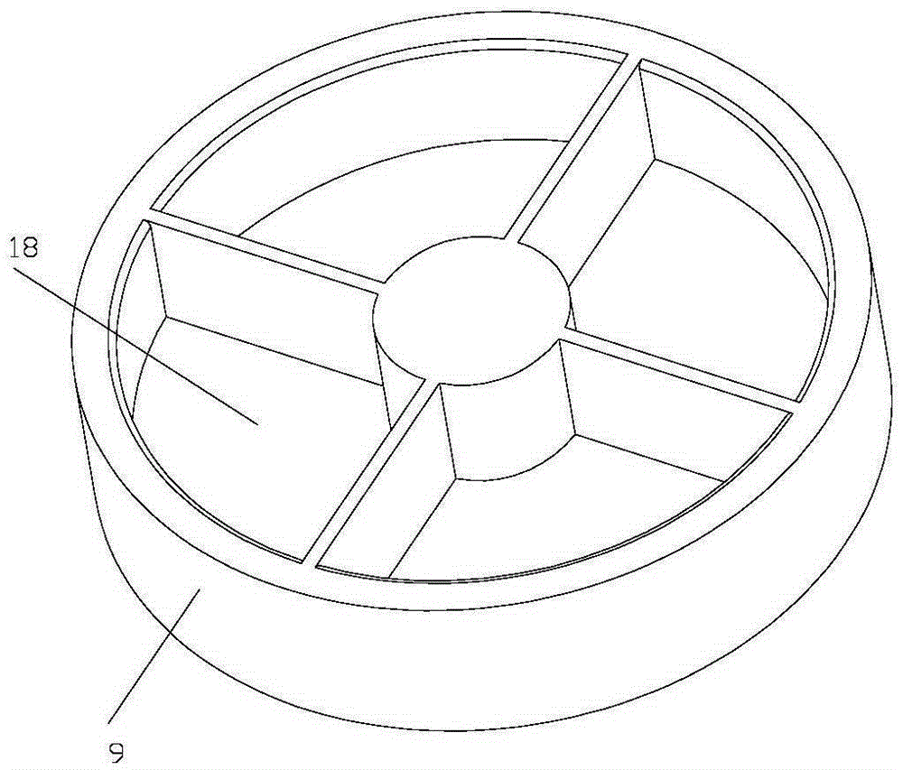
[0019] As shown in the figure, the working principle of the present invention: the first motor drives the cam to rotate continuously, and the rotation of the cam can drive the transmission rod to reciprocate clockwise and counterclockwise, and then drive the vertical plate to reciprocate up and down, and then through the bump and the swing rod The abutment of the lower end drives the swing rod to rotate clockwise and counterclockwise, and the swing rod drives the push block to move back and forth through the cooperation of the cylindrical pin and the open slot; during each left and right movement of the push block, a The ball is pushed from the barrel into one of the grooves on the turntable; when a certain number of balls are placed in this groove on the turntable, the second motor can drive the turntable to rotate to align the next groove on t...


PUM


Abstract

The invention discloses a ball automatic grouping device. The ball automatic grouping device comprises a base (1), a cam (2), a transmission rod (3), a vertical plate (4), a swing rod (5), a push block (6), a charging barrel (8) for accommodating balls (7), and a turntable (9) for receiving the balls (7) rolling from the charging barrel (8), wherein the cam (2) is rotationally connected to the base (1); a first motor for driving the cam (2) to rotate is arranged on the base (1); the middle part of the transmission rod (3) is rotationally connected to the base (1) through a first hinge point (10); one end of the transmission rod (3) is butted against the outer contour of the cam (2), and the other end is provided with an arc rack (23); and a first tension spring (14) is arranged between the transmission rod (3) and the base (1). The ball automatic grouping device is accurate in ball counting and low in labor intensity of operators.

Description

technical field [0001] The invention relates to the technical field of ball grouping in bearings, in particular to an automatic ball grouping device. Background technique [0002] During the assembly of rolling bearings, a constant number of balls need to be fitted to the cage between the inner and outer rings. In the current assembly process, the factory operators usually count the balls manually, counting the balls required for each bearing from a pile of balls. Since the surface of each ball is smooth and consistent, it is very easy to count. The wrong phenomenon, that is, it is easy to have too many or too few balls counted out, which will affect the phenomenon that the number of balls on each bearing is insufficient or there are too many balls; Reliability at work. In addition, manually counting the balls will also increase the labor intensity of the counting personnel, especially the fatigue intensity of the eyes. To sum up, the current counting of balls is prone to...

Claims


Application Information

Patent Timeline
Patent Type & Authority Applications(China)
IPC IPC(8): F16C43/06
Inventor 孙建新
Owner NEWSUN NINGBO AUTO BEARING MFG
Why Eureka
Try Eureka