Part pushing and feeding mechanism

A technology for feeding mechanism and parts, which is applied to conveyor control devices, conveyor objects, transportation and packaging, etc., can solve the problems of high labor intensity of workers, slow feeding speed, and lack of materials in the process, and achieve low labor intensity and low labor intensity. The effect of high feeding efficiency and fast feeding speed

Inactive Publication Date: 2016-01-13
GUILIN UNIV OF AEROSPACE TECH
View PDF8 Cites 1 Cited by
  • Summary
  • Abstract
  • Description
  • Claims
  • Application Information

AI Technical Summary

Problems solved by technology

Among them, the transfer of thin-walled parts is a more difficult problem. The reason is that thin-walled parts have poor rigidity and weak strength. When processing, it is not easy to guarantee the processing quality of parts
[0003] The existing feeding mechanism has more feeding methods for circular parts, disc-shaped parts, spherical parts, etc., but it is more difficult for plate-shaped thin-walled parts, especially for vertically feeding plate-shaped thin-walled parts. Large, many of them adopt the manual feeding method, not only the feeding speed is slow, but also the labor intensity of the workers is high, and the plate-shaped thin-walled parts are easy to tilt during the feeding process, resulting in material jams, which will easily lead to material shortages in subsequent processes. Failure to understand in time will affect the production progress

Method used


Image

  • Part pushing and feeding mechanism
  • Part pushing and feeding mechanism

Examples


Embodiment Construction

[0018] The principles and features of the present invention are described below in conjunction with the accompanying drawings, and the examples given are only used to explain the present invention, and are not intended to limit the scope of the present invention.

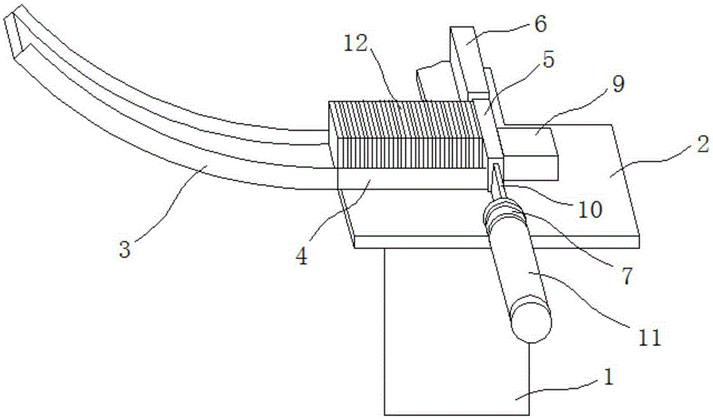
[0019] Such as figure 1 and figure 2 As shown, a feeding mechanism for pushing parts includes a frame 1, the upper end of the frame 1 is fixedly provided with a pallet 2, and the upper end of the pallet 2 is fixedly provided with a sliding feeding box 3 and a horizontal feeding box 4. The sliding feeding box 3 is placed on one side of the horizontal feeding box 4, and the side of the horizontal feeding box 4 away from the sliding feeding box 3 is fixedly provided with a pushing box 5, and the pushing box 5 and The vertical side of the axes of the horizontal feed box 4 and the slide feed box 3 is provided with a pusher device 7, and the side of the pusher box 5 away from the pusher device 7 is provided with an infr...


PUM


Abstract

The invention relates to a part pushing and feeding mechanism which comprises a rack. A supporting plate is fixedly arranged at the upper end of the rack. A downward-sliding feeding box and a horizontal feeding box are fixedly arranged at the upper end of the supporting plate. The downward-sliding feeding box is arranged on one side of the horizontal feeding box. A material push box is fixedly arranged on the side, away from the downward-sliding feeding box, of the horizontal feeding box. A push rod device is arranged on the side, perpendicular to the axes of the horizontal feeding box and the downward-sliding feeding box, of the material push box. An infrared detection device is arranged on the side, away from the push rod device, of the material push box. The push rod device can extend into the material push box to push parts to be machined to pass the infrared detection device. The infrared detection device is connected with a controller through a circuit. The controller is connected with a material push device through a circuit. The material push device is arranged on the side, away from the horizontal feeding box, of the material push box. The side, close to the material push box, of the material push device is provided with a push plate extending into the material push box. Compared with the prior art, the feeding speed is high, the labor intensity of workers is low, an alarm indicating the lack of materials can be given out timely, and feeding efficiency is high.

Description

technical field [0001] The invention relates to a feeding mechanism for pushing and adjusting parts. Background technique [0002] Thin-walled parts have been increasingly widely used in various industrial sectors because of their light weight, material saving, and compact structure. When transferring and processing thin-walled parts, there are very high requirements on the quality of thin-walled parts. Among them, the transfer of thin-walled parts is a more difficult problem. The reason is that thin-walled parts have poor rigidity and weak strength. When processing, it is not easy to guarantee the processing quality of the parts. [0003] The existing feeding mechanism has more feeding methods for circular parts, disc-shaped parts, spherical parts, etc., but it is more difficult for plate-shaped thin-walled parts, especially for vertically feeding plate-shaped thin-walled parts. Large, many of them adopt the manual feeding method, not only the feeding speed is slow, but ...

Claims


Application Information

Patent Timeline
Patent Type & Authority Applications(China)
IPC IPC(8): B65G47/82B65G43/08
Inventor 刘刚凌邵晰陈宇媚周海燕饶捷
Owner GUILIN UNIV OF AEROSPACE TECH
Why Eureka
Try Eureka