
Novel landfill method

A technology for garbage and landfill areas, applied in the direction of waste fuel, dams, solid waste removal, etc., can solve problems such as polluted water sources, soil erosion, and endangering human health

Inactive Publication Date: 2016-01-13
冯忠良
View PDF5 Cites 0 Cited by
  • Summary
  • Abstract
  • Description
  • Claims
  • Application Information

AI Technical Summary

Problems solved by technology

[0002] my country is a mountainous country, and the mountainous area accounts for more than 2 / 3 of the land area. Because there is no fallow period in agricultural production in our country, long-term cultivation leads to desertification of the land, greatly reducing the water content and oxygen content of the soil, resulting in a large amount of soil erosion. Many gullies and gullies have been formed, and today, with a daily output of 871,000 tons of domestic garbage in the country, more than 80% of urban garbage is mainly landfilled. Two-thirds of the existing 668 cities in the country are surrounded by garbage. , when there is no better garbage disposal technology, the landfill will be used for at least 30-50 years, occupying a large amount of land area, polluting our water, land and air, only unlimited investment without any return, and direct harm people in good health

Method used


Image

  • Novel landfill method
  • Novel landfill method

Examples


specific Embodiment approach

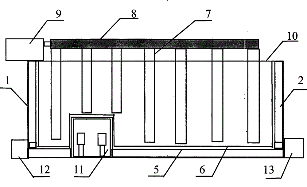
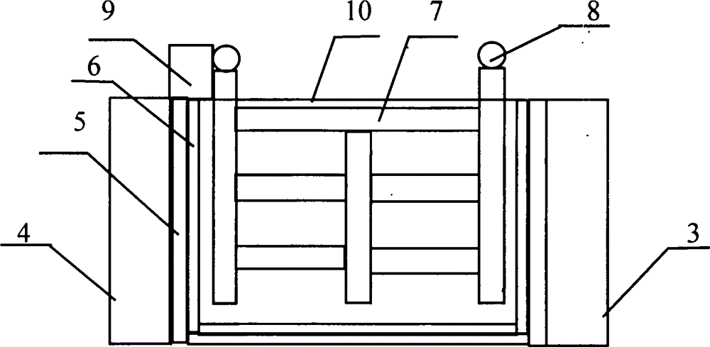
[0012] The dam body of a new technique of landfilling waste according to the present invention will be described in detail below in conjunction with the accompanying drawings. figure 1 , figure 2 They are the front view and cross-sectional view of the structure of a new landfill technology dam body. A new landfill technology dam body consists of 1 left plug, 2 right plug, 3 inner dam wall, 4 outer dam wall, 5 anti-seepage layer, 6 cushion layer, 7 gas collection pipe, 8 gas conduit, 9 gas The purification storage room is composed of 10 loam cakes, 11 gates, 12 left leachate pools, and 13, right leachate pools. Wherein, the left plug 1, the right plug 2 and the inner dam wall 3, the outer dam wall 4 or any one of the dam walls form a landfill area, and the inner wall of the landfill area is provided with anti-corrosion The seepage layer 5, the inner side of the anti-seepage layer 5 is laid with a cushion layer 6, and when the landfill garbage is compacted in the landfill are...


PUM


Abstract

The invention discloses a novel landfill method. According to the novel landfill method, garbage is compressed and sealed, and small and medium-sized water conservancy facilities are constructed so as to control water and soil loss, recover underground water resources, increase city oxygen content, and collect biogas resources in garbage. The novel landfill method comprises following steps: 1, site selection; 2, pre-building; 3, dam construction, wherein a dam body is composed of a left plug, a right plug, an inner dam wall, an outer dam wall, an impermeable layer, a bed course, gas collection pipes, gas ducts, a gas purification and storage chamber, an upper cover, a gate, a left leachate tank, and a right leachate tank; 4, dam body operation, wherein the dam body is filled with garbage, the gate is closed to retain water, aquaculture and farm irrigation are carried out, and landfill gas is used for generating electricity. If the dam bodies are constructed at flat areas or desert areas, ravines are few, a few dam bodies can be recycled, and more specifically, in autumn, the gate is opened to discharge water and sell aquatic products until the dam walls are loaded with no pressure, and then the upper cover of the dam body is unsealed, garbage sorting is carried out, residue which can be changed into fertilizer is smashed and is made into fertilizer for returning application, residue which can not be changed into fertilizer is recycled back to the market, landfill areas are cleaned, and landfill is carried out again.

Description

Technical field: [0001] The invention relates to a technique used in the field of landfill of refuse. Background technique: [0002] my country is a mountainous country, and the mountainous area accounts for more than 2 / 3 of the land area. Because there is no fallow period in agricultural production in our country, long-term cultivation leads to desertification of the land, greatly reducing the water content and oxygen content of the soil, resulting in a large amount of soil erosion. Many gullies and gullies have been formed, and today, with a daily output of 871,000 tons of domestic garbage in the country, more than 80% of urban garbage is mainly landfilled. Two-thirds of the existing 668 cities in the country are surrounded by garbage. , when there is no better garbage disposal technology, the landfill will be used for at least 30-50 years, occupying a large amount of land area, polluting our water, land and air, only unlimited investment without any return, and direct harm ...

Claims


Application Information

Patent Timeline
IPC IPC(8): B09B3/00E02B7/08
CPCY02E50/30
Inventor 冯忠良
Owner 冯忠良
Learn More