
A three-phase inverter control device and method based on virtual output impedance

A three-phase inverter and control device technology, applied in the direction of single-grid parallel feeding arrangement, etc., can solve the problems of difficult grid adjustment, inability to ignore the challenges of distribution network and micro grid, poor stability and damping effect, etc., to ensure safety The effect of reliable operation

Active Publication Date: 2017-11-03
STATE GRID CORP OF CHINA +5
View PDF2 Cites 0 Cited by
  • Summary
  • Abstract
  • Description
  • Claims
  • Application Information

AI Technical Summary

Problems solved by technology

[0002] With the global energy crisis and environmental problems becoming increasingly prominent, distributed power generation technology and micro-grid technology have received more and more attention. As the link between distributed resources and distribution network (micro-grid), grid-connected inverter The function of the controller has been deeply excavated and its beneficial role has been affirmed, but the challenges brought by the conventional control strategy itself to the safe and stable operation of the distribution network and microgrid cannot be ignored.
In particular, the conventional grid-connected inverter has a fast response speed and is difficult to participate in grid regulation. It cannot provide the necessary voltage and frequency support for the active distribution network with distributed power, let alone provide the necessary support for the relatively poor stability of the micro-grid. Damping effect, lack of an effective "synchronization" mechanism with the distribution network and microgrid

Method used


Image

  • A three-phase inverter control device and method based on virtual output impedance
  • A three-phase inverter control device and method based on virtual output impedance
  • A three-phase inverter control device and method based on virtual output impedance

Examples


Embodiment Construction

[0027] The present invention will be further described below in conjunction with the drawings. The following embodiments are only used to illustrate the technical solutions of the present invention more clearly, and cannot be used to limit the protection scope of the present invention.

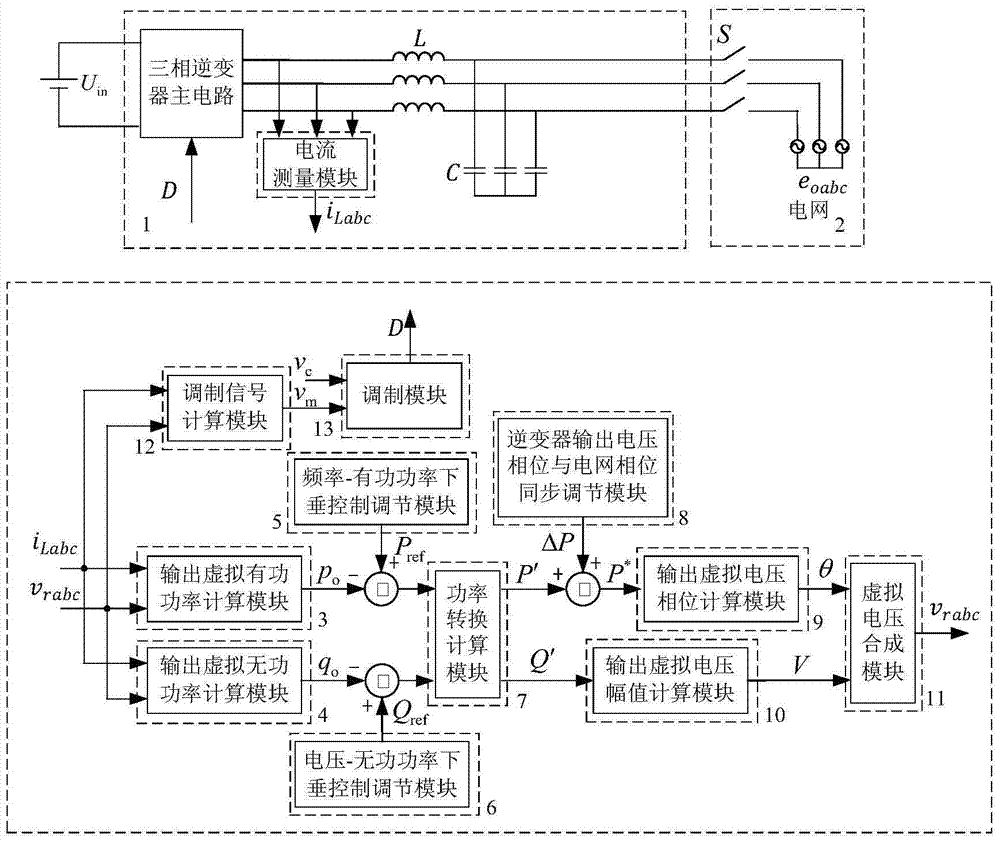
[0028] The connection relationship of this device is as figure 1 Shown.

[0029] When using, include the following steps:

[0030] 1) The three-phase inverter output filter inductor current i obtained through sampling Labc And the inverter virtual output voltage v generated by the virtual voltage synthesis module 11 rabc Input the output virtual active power calculation module 3 and the output virtual reactive power calculation module 4, and calculate the corresponding inverter virtual output active power p o And reactive power q o .

[0031] The calculation formula of output virtual active power calculation module 3 is p o =v ra ·I La +v rb ·I Lb +v rc ·I Lc (1), where v ra , V rb , V rc Respec...


PUM


Abstract

The invention discloses a three-phase inverter control device and method based on virtual output impedance, which is characterized in that it includes a three-phase inverter main circuit, a switch for grid connection, a grid module, and a current measurement module; Including output virtual active power calculation module, output virtual reactive power calculation module, modulation signal calculation module, modulation module, frequency-active power droop control adjustment module, voltage-reactive power droop control adjustment module, power conversion calculation module, inverter The output voltage phase of the generator is synchronized with the grid phase adjustment module, the output virtual voltage phase calculation module, the output virtual voltage amplitude calculation module and the virtual voltage synthesis module. The beneficial effects achieved by the present invention: the present invention realizes the operation of single and multiple inverter parallel systems in the grid-connected mode and the off-grid mode, and realizes the seamless switching function of the off-grid and grid-connected modes, ensuring the inverter The inverter system operates safely and reliably.

Description

Technical field [0001] The invention relates to a three-phase inverter control device and a method thereof, in particular to a three-phase inverter control device and a method based on virtual output impedance. Background technique [0002] With the increasingly prominent global energy crisis and environmental problems, distributed power generation technology and microgrid technology have received more and more attention, as the link between distributed resources and the distribution network (microgrid), grid-connected inverter The function of the generator has been deeply excavated and its beneficial effect has been affirmed, but the challenge that conventional control strategy itself brings to the safe and stable operation of distribution network and microgrid cannot be ignored. In particular, conventional grid-connected inverters have fast response speeds, are difficult to participate in grid regulation, cannot provide necessary voltage and frequency support for active distrib...

Claims


Application Information

Patent Timeline
IPC IPC(8): H02J3/44
Inventor 郑玉平王伟钟旭韦徽王彤宋飞
Owner STATE GRID CORP OF CHINA
Learn More