
Low-voltage power grid three-phase imbalance adjustment method based on phase-change switch

A technology for commutation switches and low-voltage power grids, which is applied in the direction of eliminating/reducing asymmetry in multi-phase networks and reducing asymmetry in multi-phase networks. Unbalanced distribution, unbalanced three-phase, etc.

Inactive Publication Date: 2016-01-06
NARI TECH CO LTD +1
View PDF4 Cites 39 Cited by
  • Summary
  • Abstract
  • Description
  • Claims
  • Application Information

AI Technical Summary

Problems solved by technology

[0002] With the development of the power system, the three-phase unbalance problem of the low-voltage distribution network is becoming more and more prominent. In the high-voltage power grid, because the load is generally a three-phase production load, the three-phase load is basically balanced, but in the low-voltage power grid, it is The power supply network is a mixed power supply network of three-phase production electricity and single-phase domestic load, and the electricity customers in the distribution network are mainly single-phase residential customers, so the connection of single-phase loads is taking up a large proportion of the entire power supply system , due to conditions and capital constraints, the extension of single-phase low-voltage power supply lines is too long, coupled with objective reasons such as uncontrollable capacity increase of single-phase users, access to high-power single-phase loads, and asynchronous power consumption of single-phase loads, etc., In the distribution network, it is very easy to cause unbalanced three-phase load distribution in the distribution area, which will have a greater negative impact on the safety, stability and economic operation of the low-voltage distribution network.

Method used


Image

  • Low-voltage power grid three-phase imbalance adjustment method based on phase-change switch

Examples


Embodiment Construction

[0029] The present invention will be further described in detail below in conjunction with the accompanying drawings and through specific embodiments. The following embodiments are only descriptive, not restrictive, and cannot limit the protection scope of the present invention.

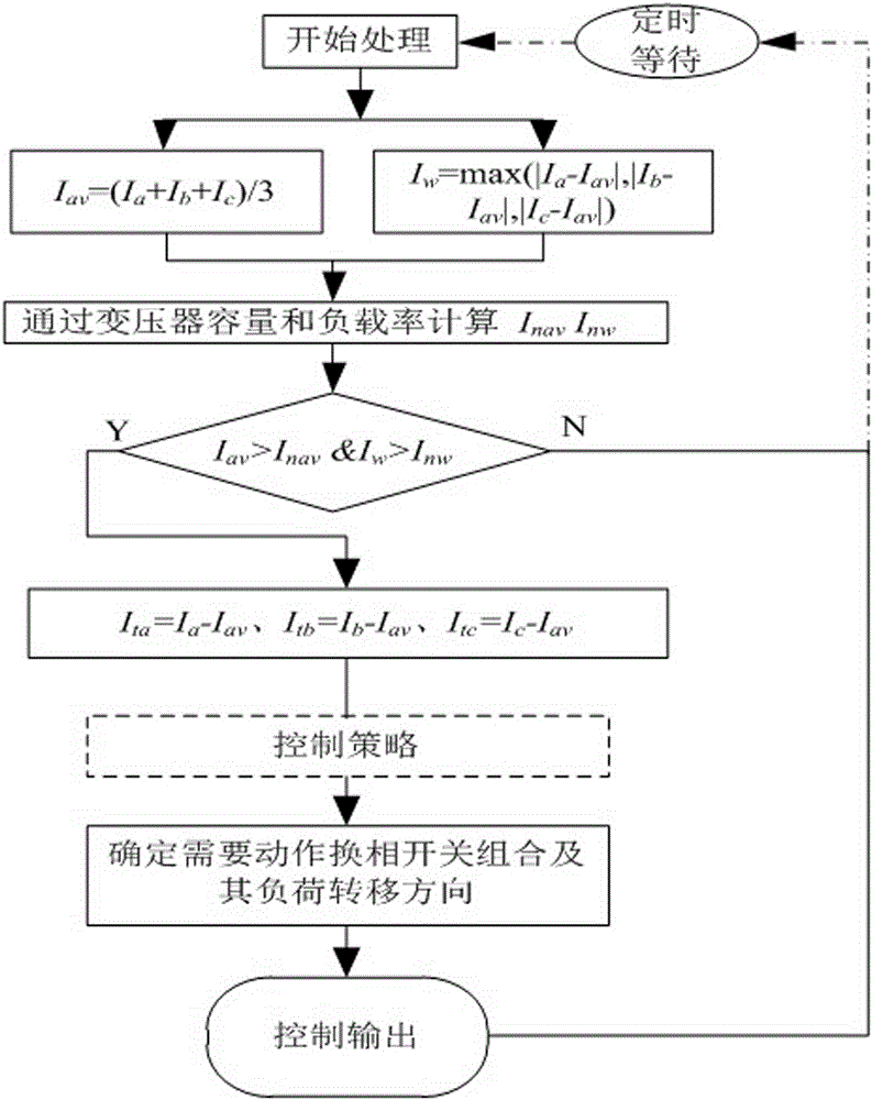
[0030] Such as figure 1 As shown, a three-phase unbalance adjustment method for a low-voltage power grid based on a commutation switch includes the following steps,

[0031] S1, the main control switch and the reversing switch are set on the transformer side and the user load side respectively, the reversing switch is connected to the user line, the main control switch controller is set, and the main control switch controller is connected to the main control switch;

[0032] In step S1, the main control switch controller and the phase change switch are installed separately, the main control switch controller is installed on the outlet side of the transformer, the phase change switch is installed on t...


PUM


Abstract

The invention discloses a low-voltage power grid three-phase imbalance adjustment method based on a phase-change switch. A difference between average current and the inter-phase maximum current is calculated, an average current fixed value and an inter-phase maximum current fixed value for starting imbalance adjustment is calculated according to transformer capacity and a load rate, three-phase transfer load is calculated, a load transfer direction is determined, the phase actually needs to transfer load out if the load which needs to be transferred is positive, the phase actually needs to receive load if the load which needs to be transferred is negative or zero, a phase-change switch which needs load transfer and a transferred target phase are determined according to the phase and the actual load of each phase-change switch, a phase-change switch action queue is generated, the phase-change switches are sequentially controlled to perform load transfer until all phase-change switches complete load transfer, and the system thus achieves the best balance state in the current condition. The method is used for low-voltage power grid three-phase imbalance treatment, the three-phase imbalance degree is reduced, voltage drop is reduced, power supply voltage treatment is improved, and line loss is reduced.

Description

technical field [0001] The invention discloses a three-phase unbalance adjustment method of a low-voltage power grid based on a commutation switch, which is used for three-phase unbalance control of the low-voltage power grid to improve power supply quality, is mainly used in the low-voltage power grid, and belongs to the field of power systems and automation thereof. Background technique [0002] With the development of the power system, the three-phase unbalance problem of the low-voltage distribution network is becoming more and more prominent. In the high-voltage power grid, because the load is generally a three-phase production load, the three-phase load is basically balanced, but in the low-voltage power grid, it is The power supply network is a mixed power supply network of three-phase production electricity and single-phase domestic load, and the electricity customers in the distribution network are mainly single-phase residential customers, so the connection of singl...

Claims


Application Information

Patent Timeline
IPC IPC(8): H02J3/26
CPCY02E40/50
Inventor 张志华周捷夏燕东蔡月明曾俊孙建东周俊王俊仁王文轩王江宁
Owner NARI TECH CO LTD
Learn More