Anti-carbon deposit injector

A fuel injector and carbon deposition prevention technology, which is applied in the direction of machines/engines, fuel injection devices, engine components, etc., can solve the problems of inability to cool the fuel injector and limited cooling parts, so as to improve the carbon deposition situation and prevent carbon deposition , the effect of improving the service life

Active Publication Date: 2017-11-07
CHANGZHOU INST OF MECHATRONIC TECH
View PDF6 Cites 0 Cited by
  • Summary
  • Abstract
  • Description
  • Claims
  • Application Information

AI Technical Summary

Problems solved by technology

[0003] Existing fuel injectors generally use a variety of cooling methods to reduce the temperature of the fuel injector, which play a role in reducing the first type of carbon deposits. However, these cooling methods have limited cooling parts and cannot uniformly cool the fuel injector. All the passages through which the gasoline flows are cooled, and most of the existing fuel injectors are controlled by solenoid valves. When the valve core and valve body are opened, the gasoline in the fuel injector will be sprayed from the nozzle, Gasoline will flow, and most of the time, the fuel injector does not inject fuel, and the gasoline in the fuel injector is in a static state, creating conditions for the decomposition and deposition of gasoline

Method used


Image

  • Anti-carbon deposit injector
  • Anti-carbon deposit injector
  • Anti-carbon deposit injector

Examples


Embodiment Construction

[0024] In order to make the content of the present invention more clearly understood, the present invention will be further described in detail below based on specific embodiments and in conjunction with the accompanying drawings.

[0025] like Figure 1~5 As shown, an anti-carbon fuel injector, which includes:

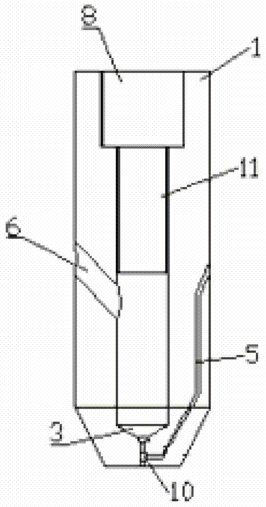
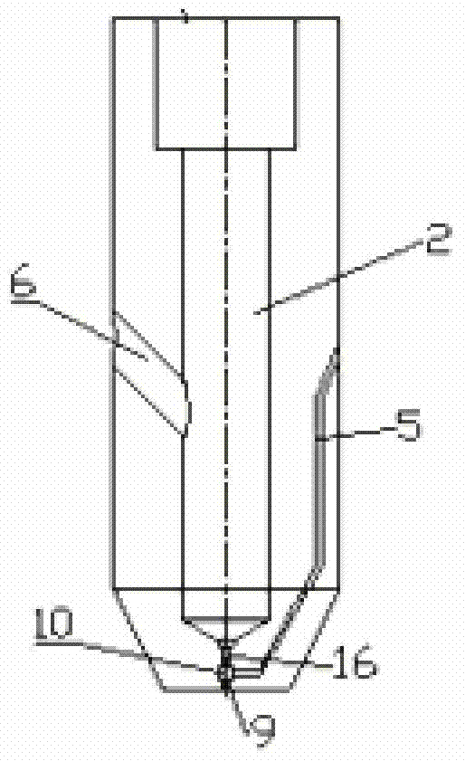
[0026] The main body, the main body has a housing 1, a plunger 11, a nozzle 9 and a controller 8, a cavity is arranged in the housing 1, and the plunger 11 is sealed and slipped in the cavity, and a cavity is opened on the housing 1 A liquid inlet hole 6 and a liquid return through hole 5, the controller 8 is connected to the plunger 11 in transmission, so that the controller 8 drives the plunger 11 to slide in the cavity, and the bottom end of the cavity is provided with a liquid outlet through hole 16, The liquid inlet hole 6 and the liquid return through hole 5 are respectively connected with the oil circuit of the fuel tank;

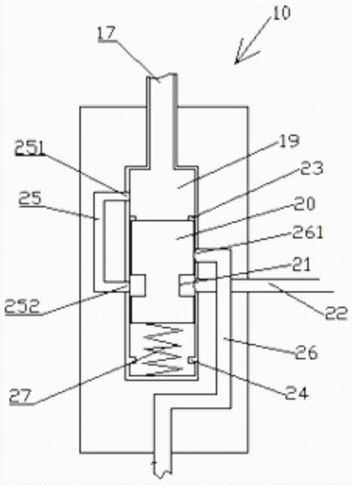
[0027] A reversing valve 10, the re...


PUM


Abstract

The invention discloses an anti-carbon fuel injector, which comprises: a main body, the main body has a casing, a plunger, a nozzle and a controller, a cavity is arranged in the casing, the plunger is sealed and slidably fitted in the cavity, and the casing is There is a liquid inlet hole and a liquid return hole, and the controller is connected to the plunger drive so that the controller drives the plunger to slide in the cavity. The bottom of the cavity is provided with a liquid outlet hole, a liquid inlet hole and a liquid return hole. The holes are respectively connected with the oil circuit of the fuel tank; the reversing valve, the position of the fuel injection state and the position of the non-fuel injection state are set on the reversing valve. When the controller drives the plunger and drives the reversing valve to the position of the non-fuel injection state, The liquid inlet hole is connected with the cavity, and at the same time, the liquid outlet hole of the cavity is connected with the liquid return hole through the reversing valve and is in a disconnected state with the nozzle; when the controller drives the plunger and drives the reversing valve to be in the oil injection state At this time, the plunger blocks the liquid inlet hole, and at the same time, the liquid outlet hole of the cavity communicates with the nozzle through the reversing valve and is in a disconnected state with the liquid return hole. The invention can effectively improve the carbon deposit of the fuel injector and increase the service life of the fuel injector.

Description

technical field [0001] The invention relates to an anti-carbon deposit injector. Background technique [0002] At present, the carbon deposits in the fuel injectors of in-cylinder direct injection engines mainly include two situations: the carbon deposits formed in the fuel injectors after gasoline is thermally decomposed in the fuel injectors, and the carbon deposits formed in the cylinders after gasoline is not fully burned. The carbon deposit formed by the accumulation of particles or colloids at the valve body of the fuel injector, on the one hand, needs to be cooled for the fuel injector, so as to reduce the temperature of the gasoline passage, reduce the temperature of the gasoline flowing through the passage, and reduce the internal temperature of the fuel injector. The stagnation time of gasoline flow reduces the deposition of gasoline after thermal decomposition; on the other hand, it separates the precise control valve in the injector from the high-temperature gas ...

Claims


Application Information

Patent Timeline
Patent Type & Authority Patents(China)
IPC IPC(8): F02M51/06F02M61/04
Inventor 任萍丽鲁明张炎李彦
Owner CHANGZHOU INST OF MECHATRONIC TECH
Why Eureka
Try Eureka