
Scribing Device

A scoring line and loader technology, applied in glass cutting devices, fine working devices, transportation and packaging, etc., can solve problems such as interference, inability to completely score the scheduled line S2 to the end, inconvenience, etc.

Active Publication Date: 2016-01-06
MITSUBOSHI DIAMOND IND CO LTD
View PDF7 Cites 11 Cited by
  • Summary
  • Abstract
  • Description
  • Claims
  • Application Information

AI Technical Summary

Problems solved by technology

However, if the width of the terminal material region T is reduced to 3mm, as shown in FIG. Line S1
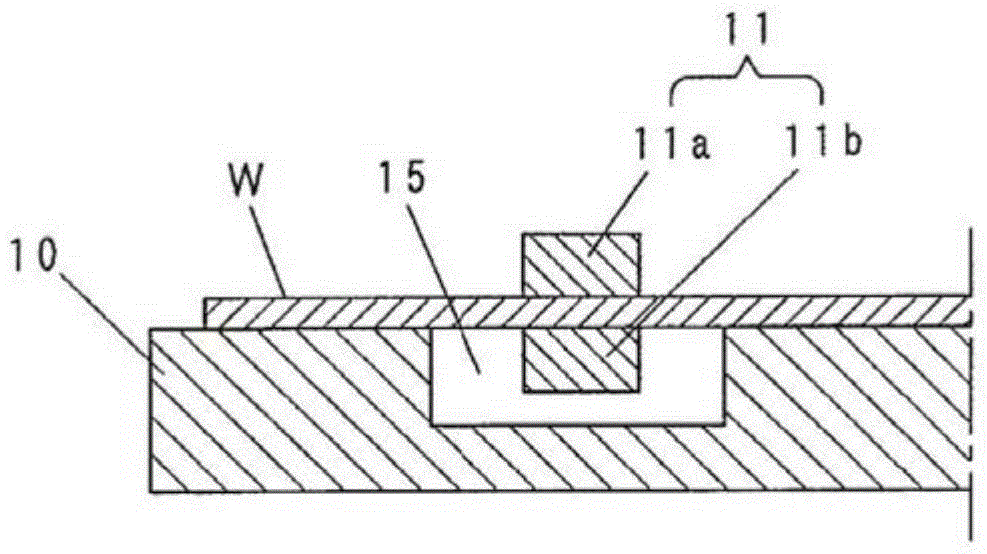
[0009] Also, the same applies to the case of marking the planned marking line S2 in the Y direction, such as Figure 8 If the position of the jaws 11 shown is placed on the planned marking line S2 in the Y direction that must be processed, the cutter wheel 23 will be interfered by the jaws 11 so that the planned marking line S2 in the Y direction cannot be completely scored. at last
[0010] This shows that the above-mentioned existing marking device obviously still has inconvenience and defects in structure and use, and needs to be further improved urgently.
In order to solve the above-mentioned problems, the relevant manufacturers have tried their best to find a solution, but for a long time no suitable design has been developed, and the general product has no suitable structure to solve the above-mentioned problems. This is obviously the relevant industry. Urgent problem

Method used


Image

  • Scribing Device
  • Scribing Device
  • Scribing Device

Examples


Embodiment Construction

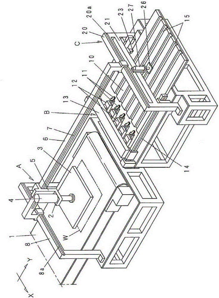
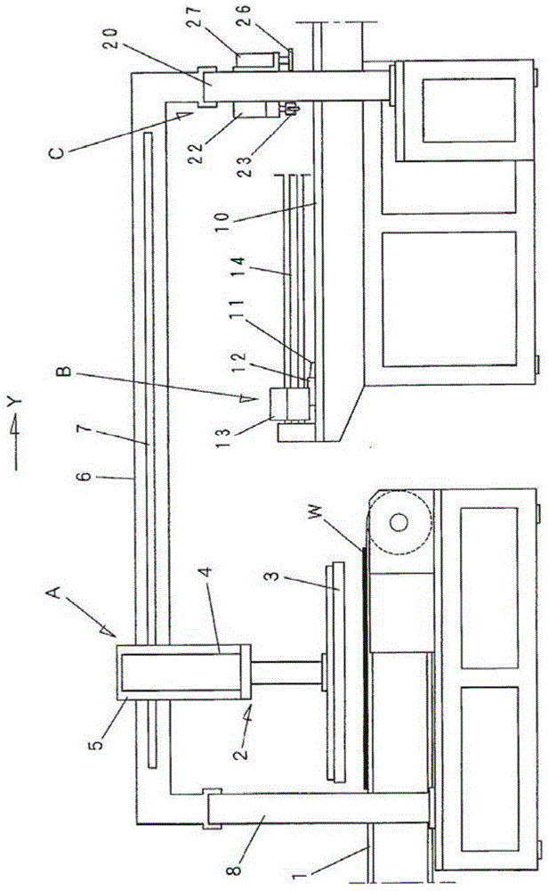
[0049] In order to further explain the technical means and effects of the present invention to achieve the intended purpose of the invention, the specific implementation, structure, characteristics and features of a marking device proposed according to the present invention will be described below in conjunction with the accompanying drawings and preferred embodiments. Efficacy, detailed as follows.

[0050] In the following, refer to Figure 1-9 The details of the scribing device of the present invention will be described. The substrate W to be scribed in the present invention, as shown in FIG. 6( a ), is divided into six units by the planned scribing line S1 in the X direction and the planned scribing line S2 in the Y direction that are perpendicular to each other. The substrate area W1, and the terminal material area T around the four sides. In this embodiment, the width of the terminal material region T is set to about 3 mm.

[0051]The scoring device of the present inv...


PUM


Abstract

The invention provides a scribing device. The scribing device is used for ensuring the width of an end material region of a substrate is approximately equal to the width of a gripping area of a clamping claw, the end material region is not interfered by the clamping claw, and the substrate can be scribed along the planned scribing line. The scribing device comprises the following components: a loader (A), which is used for conveying the substrate (W) from a first position to a second position at a downstream side of a substrate conveying direction, and an upstream side end part of the substrate (W) which is conveyed to the second position is clamped by the clamp claw (1) in a grasping state; a grasping and conveying unit for conveying to a scribing unit (C) equipped at a downstream side; and a cutter wheel (23) of a scribing unit (C) for scribing the planned scribing line (S2) at a Y direction on the surface of the substrate (W) conveyed to the scribing unit (C). The loader (A) comprises a suction conveying component (2) for selecting the substrate (W), and the loader (A) and the suction conveying component (2) can move at an X direction at the same time.

Description

technical field [0001] The present invention relates to a scribing device for a brittle material substrate, which processes a scribing line (groove) for breaking along a scribing predetermined line on the surface of a brittle material such as glass, silicon, and ceramics. In particular, the present invention relates to a scribing device for a brittle material substrate in which terminal material regions are formed at four-sided peripheral portions. Background technique [0002] In general, when cutting a unit substrate from a brittle material substrate (hereinafter, simply referred to as "substrate"), as Figure 10 As shown, first, the scribing line is processed along the X-direction scribing line S1 and the Y-direction scribing line S2 that are perpendicular to each other on the surface of the substrate W', and the next step is to process the scribing line along the above A plurality of scribe lines S1 and S2 are used to scribe and cut a unit substrate to be a product. In ...

Claims


Application Information

Patent Timeline
Patent Type & Authority Applications(China)
IPC IPC(8): B65G47/91C03B33/02B28D1/24B28D5/02B28D7/00
CPCB28D5/0058C03B33/033C03B33/105
Inventor 得永直
Owner MITSUBOSHI DIAMOND IND CO LTD
Learn More