
Wear-resisting ball surface treating device

A surface treatment device and technology of wear-resistant balls, which are applied in the field of wear-resistant balls, can solve problems such as increased dust, unremoved rust, and polluted working environment, and achieve the effects of improving work efficiency, reasonable structure, and energy saving

Inactive Publication Date: 2016-01-06
NINGGUO SOUTHERN WEAR RESISTANT MATERIALS
View PDF6 Cites 4 Cited by
  • Summary
  • Abstract
  • Description
  • Claims
  • Application Information

AI Technical Summary

Problems solved by technology

[0002] When the wear-resistant steel ball is eroded by rainwater, the wear-resistant steel ball will be corroded after being damp, and the corroded steel ball cannot be used for grinding operations. Therefore, it is necessary to use the inertia ball machine to install the wear-resistant steel ball into the inertia ball. Inside the machine, the inertial ball machine rolls, using the collision and friction between the steel balls to remove the burrs and other defects on the surface of the wear-resistant steel ball. However, when the inertial machine removes the rust debris on the surface of the wear-resistant steel ball, a large amount of The dust and dust will pollute the working environment and bring great inconvenience to the staff. A large number of rusty debris will accumulate in the inertial ball machine. A large number of rusty debris will not only easily cause blockage in the machine body, but also the rusty debris will further wear and tear during the working process of the machine body , leading to an increase in dust, which requires regular cleaning, which reduces the efficiency of steel derusting and increases the workload of staff
The shape and size of the steel balls are inconsistent, and the contact area between most of the steel balls is small. After a long time of collision between the steel balls, some areas of the steel balls are worn, but the rust in some areas is still not removed. It is necessary to manually clean the steel balls. Carrying out secondary derusting also increases the workload of the staff

Method used


Image

  • Wear-resisting ball surface treating device
  • Wear-resisting ball surface treating device

Examples


Embodiment Construction

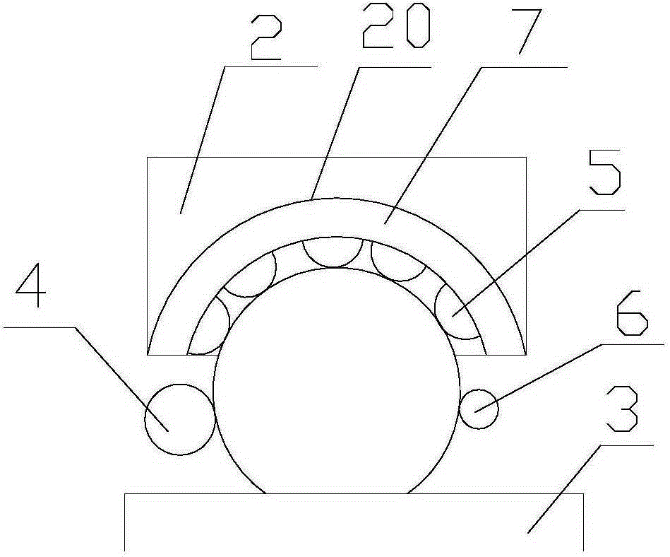
[0021] refer to figure 1 , figure 2 , a wear-resistant ball surface treatment device proposed by the present invention, comprising: a bracket 1, a rust removal structure 2, a plurality of first rollers 3, a second roller 4, a first driving mechanism and a second driving mechanism;

[0022] A plurality of first rollers 3 are installed on the support 1, and are arranged parallel to each other on an inclined plane to form a transport track 30. There is a gap between adjacent first rollers 3, so that the sundries on the transport track 30 can pass through the gap. drop in.

[0023] The first driving mechanism is respectively connected with the first roller 3 and drives it to rotate around the central axis; the wear-resistant ball A on the transport track 30 rolls from the high end to the low end, and the rotation direction of the first roller 3 moves with the wear-resistant ball A in the opposite direction. In this way, the wear-resistant ball A is under the action of gravity,...


PUM


Abstract

The invention discloses a wear-resisting ball surface treating device. The wear-resisting ball surface treating device comprises a support, a rust removing structure, a plurality of first rollers, a second roller, a first driving mechanism and a second driving mechanism. The multiple first rollers are installed on the support and arranged on an inclined plane in parallel to form a conveying rail. The first driving mechanism is connected with the first rollers and drives the first rollers to rotate around a central shaft. A wear-resisting ball on the conveying rail rolls from the higher end to the lower end. The rotation direction of the first rollers is opposite to the movement direction of the wear-resisting ball. According to the wear-resisting ball surface treating device, all-dimensional rotation of the wear-resisting ball can be achieved under the action of self-weight and the friction force by means of the conveying rail and the second roller which are arranged obliquely, so that during rolling, relative friction is achieved between the whole ball surface and the grinding structure, and the grinding effect is achieved. The wear-resisting ball surface treating device is reasonable in structure, the gravity action is utilized sufficiently, energy sources are saved easily, and the working efficiency is improved.

Description

technical field [0001] The invention relates to the technical field of wear-resistant balls, in particular to a surface treatment device for wear-resistant balls. Background technique [0002] When the wear-resistant steel ball is eroded by rainwater, the wear-resistant steel ball will be corroded after being damp, and the corroded steel ball cannot be used for grinding operations. Therefore, it is necessary to use the inertia ball machine to install the wear-resistant steel ball into the inertia ball. Inside the machine, the inertial ball machine rolls, using the collision and friction between the steel balls to remove the burrs and other defects on the surface of the wear-resistant steel ball. However, when the inertial machine removes the rust debris on the surface of the wear-resistant steel ball, a large amount of The dust and dust will pollute the working environment and bring great inconvenience to the staff. A large number of rusty debris will accumulate in the inert...

Claims


Application Information

Patent Timeline
IPC IPC(8): B24B27/033B24B11/02
CPCB24B27/033B24B11/02
Inventor 熊夏鸣
Owner NINGGUO SOUTHERN WEAR RESISTANT MATERIALS
Learn More