Protective cover for cutting gun

A technology of protective cover and cutting torch, applied in the field of protective cover, can solve problems such as problems that cannot be solved from the source, and achieve the effects of simple structure, economical and practical, and quick installation.

Inactive Publication Date: 2016-01-06
TONGCHENG LIQIONG METAL PROD
View PDF5 Cites 7 Cited by
  • Summary
  • Abstract
  • Description
  • Claims
  • Application Information

AI Technical Summary

Problems solved by technology

But neither can solve the problem from the source

Method used


Image

  • Protective cover for cutting gun
  • Protective cover for cutting gun
  • Protective cover for cutting gun

Examples


Embodiment Construction

[0016] In order to make the object, technical solution and advantages of the present invention clearer, the present invention will be further described in detail below in conjunction with the accompanying drawings and embodiments. It should be understood that the specific embodiments described here are only used to explain the present invention, not to limit the present invention.

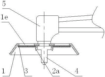
[0017] Described a kind of protective cover that is used for torch, as figure 1 As shown, it includes a protective cover 1 and a black glass 3, the black glass 3 is fixed on the protective cover 1 by a collar 2, and the collar 2 is fixed on the protective cover 1;

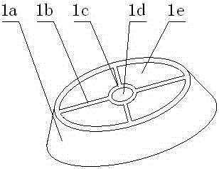
[0018] Such as figure 2 As shown, the protective cover 1 includes a cover body 1a, a fixed ring A1c, and a window 1e. The fixed ring A1c is connected to the cover body 1a by ribs 1b, and the fixed ring A1c has a fixing hole A1d;

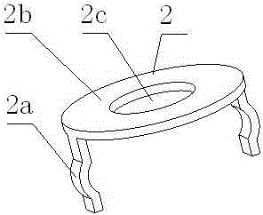
[0019] Such as image 3 As shown, the collar 2 includes a fixed ring B2b and a clip bar 2a, the number ...


PUM


Abstract

The invention relates to a protective cover for a cutting gun. The protective cover comprises a protective cover body and black glass. The black glass is fixed to the protective cover body through a clamping ring which is fixed to the protective cover body. The protective cover body comprises a main cover body, a fixing ring A and a sight window. The fixing ring A and the main cover body are connected through ribs. A fixing hole A is formed in the fixing ring A. The clamping ring comprises a fixing ring B and clamping strips. An arc protrusion is arranged at the position, facing the outside, of each clamping strip, and the clamping strips on the clamping ring are evenly distributed on the outer side of the clamping ring. A cutting torch is placed in the fixing hole A in the protective cover body and a fixing hole B in the clamping ring, the cutting torch and a cutting gun head are fastened, and therefore the fixing ring A and the fixing ring B are fixedly clamped between the cutting torch and the cutting gun head through the cutting torch. The protective cover is simple in structure, economical, practical and rapid to mount, can play a role of preventing splashing and does not affect observation of the moving direction of the cutting torch by an operator, so that the precision of gas cutting is guaranteed.

Description

technical field [0001] The invention relates to a protective cover, in particular to a protective cover installed on a torch. Background technique [0002] The cutting torch is a tool for gas cutting. It uses the high-speed gas flame generated by the mixed combustion of acetylene and oxygen to blow and melt metal materials, so that the molten metal drops to form a cut. During the cutting process, the rust and impurities on the steel surface are heated by the high-temperature flame, which is prone to splash and may burn the operator. During gas cutting, in order to ensure the accuracy of the cutting direction and route, always pay attention to the direction of the cutting nozzle during gas cutting. However, the glare from the high-temperature flame at the cutting nozzle not only affects the observation effect, but also damages the operator's eyesight. [0003] Faced with the above problems, operators often solve them by wearing sunglasses and protective clothing. But none ...

Claims


Application Information

Patent Timeline
IPC IPC(8): B23K7/10
CPCB23K7/10
Inventor 王丹
Owner TONGCHENG LIQIONG METAL PROD
Why Eureka
Try Eureka